GPS modules are one of the most essential components of IoT devices. They are primarily used to determine the coordinates of the current location and much more. In this tutorial, we will explore troubleshooting techniques for GPS modules, especially the popular NEO-6M GPS Module from Ublo. Also please note that we have written this tutorial assuming that you are using the NEO 6M GPS module with Arduino UNO, but you can also follow the instructions for other development boards like ESP32, Arduino Nano, or even Raspberry Pi. We are just checking the working of the NEO 6M GPS module by connecting it to a USB to UART converter, once we have verified that the hardware is working we can follow a simple Arduino GPS Interfacing tutorial to get our GPS projects working.
Neo 6M GPS Module Quick Troubleshooting Steps
If your Neo 6M GPS module is not working, here are 5 important things you should check
Check power connections (3.3V to 5V)
Verify antenna connection
Confirm baud rate settings (9600)
Test NMEA output
Verify satellite signal reception
The table below also summarizes the common problems faced when using Neo 6M GPS module and its solution
If you have tried the above quick fixes and even after that your Neo 6m GPS module is not working, don't worry. We are going to take a deep dive into the module and share our learning and experience with you so that you will be able to get it working in no time. So, let's get started with the basics.
U-blox Neo 6M GPS Module - Basics
Neo 6 series is the most popular GPS module from U-blox, widely used for positioning and navigation applications. It features a compact design and delivers high-accuracy GPS data, supporting a range of uses such as robotics, drones, and IoT projects.
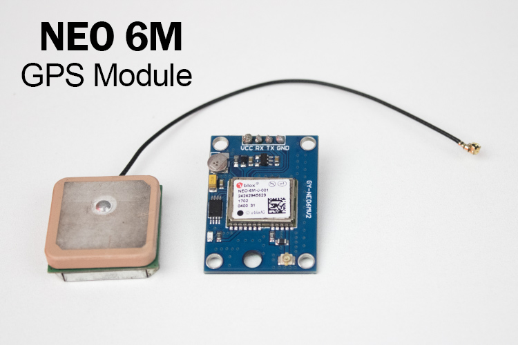
The module is equipped with the u-blox 6 engine, which provides fast and reliable satellite positioning with support for multiple navigation systems. It also offers efficient power consumption, making it ideal for battery-powered applications. With its ability to track multiple satellites, the NEO-6M is a versatile and reliable GPS solution for various projects.
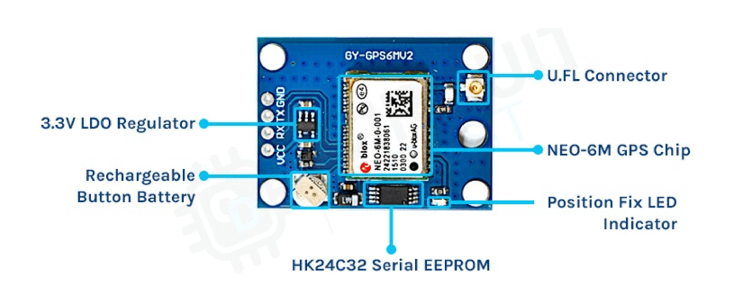
However, one issue with the NEO-6M GPS module is that the version with crystal and ROM has reached its end-of-life. This means there is no more official support from the U-blox team. It is recommended to consider their advanced series if you are working on new products. That doesn’t mean the NEO-6M is unusable; it’s simply an older generation.
Now that we’ve covered the basics of the Neo-6M, let's proceed with the troubleshooting methods.
NEO 6M GPS Module Not Working?
If you have tried your first project with NEO 6M GPS Module and things are not working the way you expect them to, don't worry you are not alone. We at circuitdigest, have built a lot of projects using NEO 6M GPS Module and we often face problems, which is why we have created this comprehensive troubleshooting guide for you.
Our plan is to connect the GPS module to the computer using any UART-to-USB method and confirm the origin of the issue-whether it is hardware or software-related. Once the issue is identified, we can solve it appropriately.
Neo 6M GPS Module Connection Problems
The most common problem when using NEO6M GPs module occurs with wiring, so first let's ensure proper connections.
As I have a CP2102-based USB to UART bridge, I am using that. Below, you can see the proper circuit diagram that needs to be followed. Kindly make sure you are using fine jumper wires to make the connection. Sometimes, there might also be a problem. Similarly, the antenna wire should also be checked.
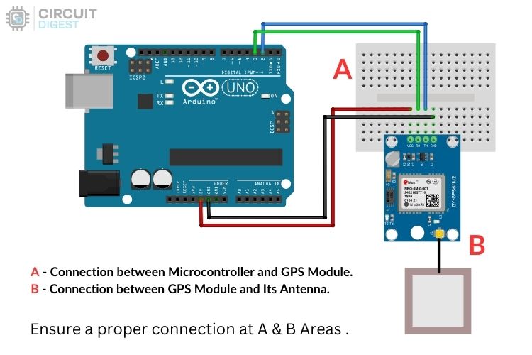
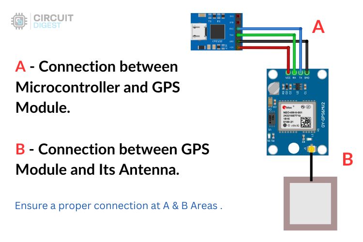
There are two key areas to focus on when connecting your NEO 6M GPS Module with any development board like Arduino:
A. The connection between the USB to UART Bridge (or Microcontroller) and the GPS Module:
Usually, there are four wires, two for signals and two for power. The module includes an inbuilt voltage regulator, so it accepts a voltage range of 3.3V to 5V. The signal pins, TX and RX, should be connected to RX and TX of the USB-UART Bridge, respectively.
B. The connection between the Antenna and the GPS Module:
Typically, the module has an IPEX connector. If you suspect issues, clean the connectors with isopropyl alcohol and fix them firmly. Check for loose contacts, and if necessary, use small pliers to slightly bend the metal clamping part of the connector to ensure a secure connection.
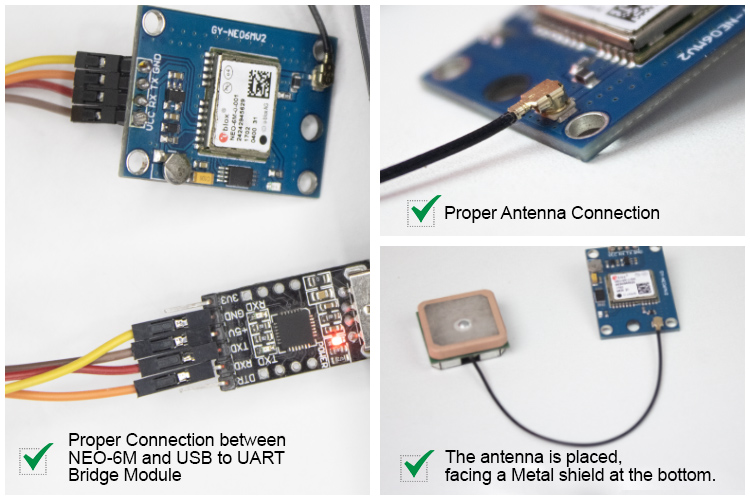
Once all connections are perfect, the module should work fine. If not, let’s move to the next step.
Neo 6M GPS Module Not Responding (No Output)
Assuming there is no connection issue, we will now check the NMEA output from the UART port of the NEO-6M.
The NEO-6M module, by default, outputs NMEA data through its transmitting pin without any triggers. To view the data, you need to set the baud rate of your serial monitoring program to the default baud rate of the NEO-6M, which is “9600”.
Next, let’s move to the hardware section.
If you have a USB to Serial Bridge/Debugger, you can use it. Alternatively, you can use an Arduino Uno or any other microcontroller as a USB to UART Bridge. The code for converting the Arduino Uno to a USB UART Bridge can be found in the Git repository.
With a working USB-to-Serial Converter, connect the circuit as discussed earlier. Next, identify the communication port number of the connected device, e.g., “COM3.”
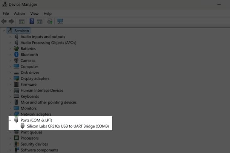
Open the Arduino IDE and next SerialMonitor. Set the baudrate to “9600”. If the module is functioning, you should see text being continuously printed. This indicates the module is working fine and has no significant damage.
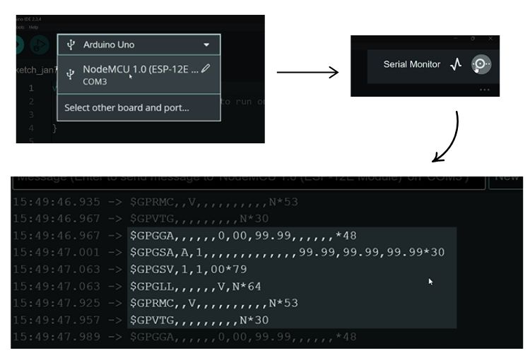
If no data is printed, it likely means the module is not receiving enough satellite signals. At least four satellite signals are needed to fix a location accurately. Without a location fix, there will be no data in the NMEA sequence.
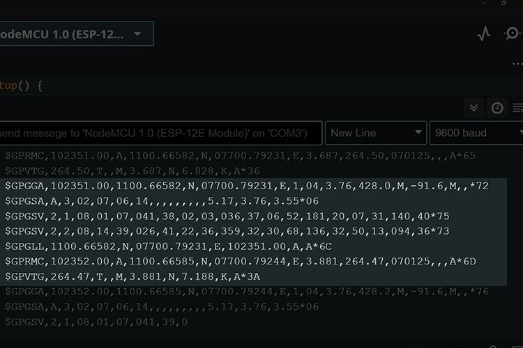
Once enough satellites are detected, the LED on the GPS module will start blinking at a 1-second interval. If there is no blinking, the module is still searching for a satellite signal. Now lets move to the data Analysis.
How to Fix NEO-6M GPS Connection Issues
If everything above passes successfully, we now need to check for the location data in the NMEA sequence.
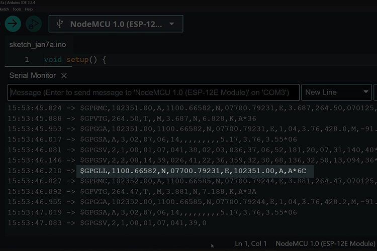
In the series of data, the sentence that starts with $GPGLL contains the location and time data. The rest also has some important information used by advanced users.
The $GPGLL sentence has a format like:
$GPGLL, latitude, latitude direction, longitude, longitude direction, time, validity, mode*checksum
Breakdown of the GPGLL Sentence:
Below is the breakdown of a $GPGLL sentence highlighted in the above image.
Latitude: 1100.66582 - This represents the latitude in degrees and minutes. It’s 11 degrees and 00.66582 minutes North.
Latitude Direction: N - This indicates the latitude is in the Northern Hemisphere (for the Southern Hemisphere, it would be S).
Longitude: 07700.79231 - This represents the longitude in degrees and minutes. It’s 77 degrees and 00.79231 minutes East.
Longitude Direction: E - This indicates the longitude is in the Eastern Hemisphere (for the Western Hemisphere, it would be W).
Time: 102351.00 - This is the UTC time in the format of HHMMSS.sss (10:23:51.000 UTC).
Validity: A - This means the data is valid, indicating the GPS has a good satellite fix (if it were V, it would indicate the data is invalid).
Mode: A - This indicates Autonomous mode, meaning the GPS is using its own internal calculations for the position.
Checksum: *6C - This is for error checking to ensure the data has not been corrupted.
In conclusion, we have gained valuable insights into using the NEO-6M GPS module correctly and efficiently obtaining data from it. Understanding the structure of NMEA sentences and how to interpret the information provided by the GPS allows us to utilize the module in various applications such as navigation, location tracking, and time synchronization.
For further learning, you can refer to the FAQ section, where additional resources and answers to common questions will help you dive deeper into the topic and expand your understanding.
Common GPS Module Problems and Solutions
LED Not Blinking on the NEO-6M?
The single LED on the NEO-6M module is not a power indicator but serves a status indicator. The LED is connected to the Time Pulse Output pin of the NEO-6M module. By default, it acts as a position-fix indicator. Here is how the LED on NEO 6M GPs Module behaves
No blinking: The NEO-6M module is searching for a satellite signal.
Blinking every second: The NEO-6M module has detected enough satellites to fix its position.
If your module’s LED blinks at a 1-second interval, it is functioning correctly.
NEO-6M GPS Module not Connecting to Satellite?
The placement of the antenna is crucial for the proper reception of signals from satellites. Follow these guidelines to ensure your NEO 6M GPS Module can connect to the satellite
Position the radiating side of the antenna (top metallic patch) facing upward towards the sky.
Avoid being close to obstructions such as walls, roofs, or metal objects that can block or reflect GPS signals.
Place the GPS module on a non-conductive surface to prevent signal distortion.
Keep the antenna away from sources of electromagnetic interference (EMI) such as Wi-Fi routers, motors, or high-power electronics.
If you are using multiple modules, maintain a distance from other antennas to prevent cross-interference.
Ensure the antenna cable is not bent sharply or exposed to damage, as this can degrade signal quality.
If used outdoors, protect the antenna from environmental factors like rain, dust, or extreme temperatures using appropriate enclosures.
Troubleshooting GPS Module NMEA Data
National Marine Electronics Association (NMEA) is a standard data format widely used in GPS systems. The $GPGLL sentence in NMEA data provides essential geographic positioning information, including latitude, longitude, UTC time, and fix validity. Here's the format and an example:
$GPGLL, latitude, latitude direction, longitude, longitude direction, time, validity, mode*chec sum
For example:
Below is the data received from the GPS module which looks similar to the above dat formate.
$GPGLL, 1100.66265, N, 07700.78513, E, 073843.00, A, A*6B
However, there are more sentences, such as DTM, GBS, GGA, GLL, GPQ, GRS, GSA, GST, GSV, RMC, THS, TXT, and VTG. To learn more about these, kindly refer to the official U-blox Receiver Description.
Explore more about Neo 6M GPS Module
With this troubleshooting guide, we hope you were able to get your NEO 6M GPS Module working. Here are a few of our other tutorials that you can check out to learn more about the NEO 6M GPS Module and what you can build using it.
How to use Neo 6M GPS module with ESP32 Development Board
Learn how to use your Neo 6M GPS module with ESP32 Development Board. This article covers the basics, circuit diagram, and the code to connect your Neo 6M GPS module with ESP32 and read the location data.
Interface Neo 6M GPS module with Atmega16/32 AVR Microcontroller
This article explains how to use the NEO 6M GPS module with an AVR microcontroller, namely the ATmega16. It covers the circuit diagram and code to read the GPS data and display the latitude and longitude data on a 16x2 LCD display.
How to Select Best GPS Modules for Vehicle or Asset Tracking Projects
This article will help you find the best GPS modules from the choices available in the market. We will discuss the features and specifications of different types of GPS modules and when to use them for specific applications.
How to use Neo 6M GPS Modules with NodeMCU
This tutorial shows step-by-step instructions on how to use your Neo 6M GPS module with a NodeMCU development board. The project provides a detailed guide with code and circuit diagram to read the GPS data and display the latitude and longitude values on a web server.
Build your own GPS Location Tracker using Neo 6M GPS Module and Google Maps
Learn how to build your own GPS Tracker device using the Neo 6M GPS module and NodeMCU. This project guide shows you how to read the GPS data at specific intervals and display the location as a route on Google Maps.

