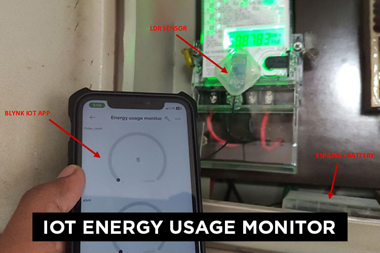
This is an IOT device with an LDR light sensor and a microcontroller with WIFI connectivity ESP8266/ESP32. Commercial household Energy meters have a LED on them which blinks/pulses according to the energy consumption. For every 3200 LED pulses it is equated to 1KWh of energy consumption. This ENERGY USAGE MONITOR device keeps count of these pulses and with this pulse count it calculates the KWh and in turn calculates the number of units of energy consumed (1KWh = 1unit).
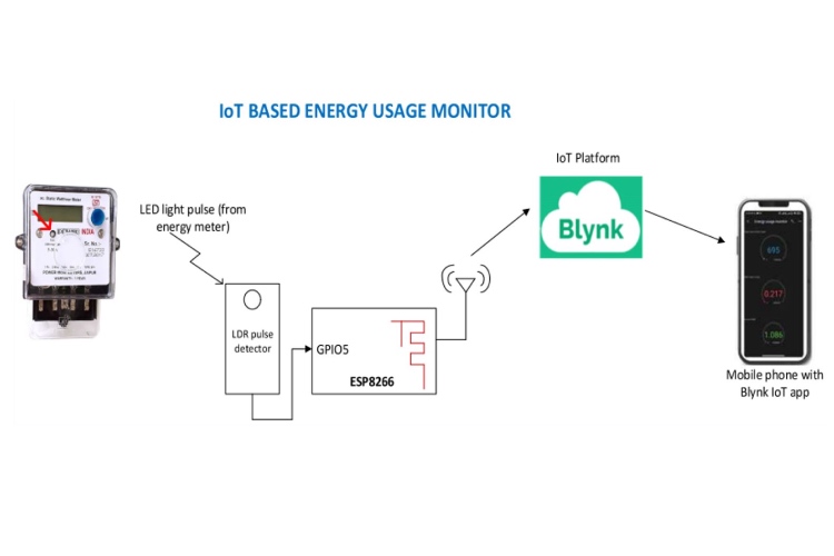
This is a small and light weight IOT device which is stuck/glued on to the Energy meter with LDR sensor facing on to the energy meters LED. ESP8266/ESP32 keeps track of the pulse count and sends the count periodically to Blynk IOT platform over WIFI. With this pulse count in the IOT platform/webpage, energy consumption, units count and expected electric bill are calculated and shown to the user.
This makes the users aware of their energy consumption habits and keep track of their energy consumptions and alarm the users if they are over consuming the energy.
List of Components:
- ESP8266/ESP32
- LDR Sensor
- 3.7V Battery
- TP4056 battery charger with protection
- LT1303CN8-5#PBF Boost regulator – Analog devices
- AD8541ARTZ-REEL Opamp – Analog devices
- Header connectors
- Passive components – Resistors, Capacitors
System Block Diagram:
Schematics:
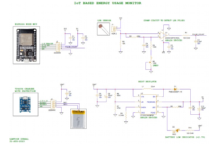
Schematics consists of an LDR sensor pulse detection circuit implemented with an Opamp as a comparator. -VE terminal of Opamp is connected to input signal from LDR sensor and the same signal is also connected to +VE terminal of the Opamp through a low pass filter. Output of the Opamp goes high whenever there is a difference in the inputs, this will happen when the LDR sensor signal has some dip. Potentiometer is used to bias the output to low by default when there is noise.
Output of this Opamp circuit is connected to a GPIO pin of ESP8266 NODE MCU which keeps track of the pulse counts and periodically upload the same pulse count data to Blynk IoT platform.
This whole system is powered from 5V which is derived from a 3.7V lithium ion battery. This battery can be recharged through TP4056 charger with protection module. 3.7V from battery is boosted to 5V through a Boost regulator.
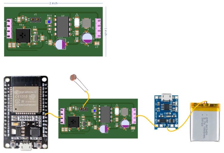
PCB:
Setup Images:

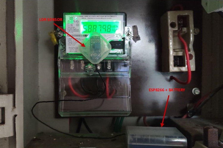
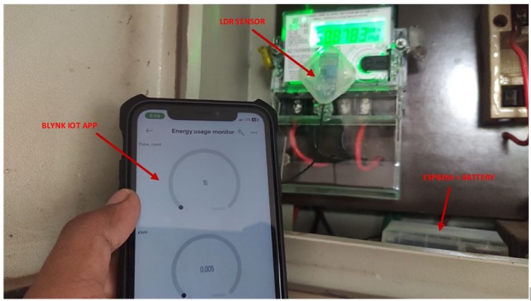
Complete Project Code
/* Fill-in information from Blynk Device Info here */

#define BLYNK_TEMPLATE_ID           "********"

#define BLYNK_TEMPLATE_NAME         "Energy usage monitor"

#define BLYNK_AUTH_TOKEN            "********"

#include <ESP8266WiFi.h>

#include <BlynkSimpleEsp8266.h>

// Your WiFi credentials.

// Set password to "" for open networks.

char ssid[] = "*******";

char pass[] = "*******";

int    val = 0;

int    currentState = 0;

int    previousState = 0;

int    inputpin = 5;

float  pulseCount = 0;

float  constant = 3200;

float  inr = 7;

float  Amount = 0;

float  KWH = 0;

BlynkTimer timer;

void setup()

  {

  pinMode (5, INPUT);

  Blynk.begin(BLYNK_AUTH_TOKEN, ssid, pass);

  timer.setInterval(1000L, myTimerEvent);

  }

  void myTimerEvent()

  {

  Blynk.virtualWrite(V0, pulseCount);

  Blynk.virtualWrite(V1, KWH);

  Blynk.virtualWrite(V2, Amount);

  }

  void loop()

  {

  Blynk.run();

  timer.run(); // Initiates BlynkTimer

  val = digitalRead(inputpin);

  if (val == HIGH)

  {

  currentState = 1;

  }

  else

  {

  currentState = 0;

  }

  if(currentState != previousState)

  {

  if(currentState == 1)

  {

  pulseCount = pulseCount + 1;

  }

  previousState = currentState;

  }

  KWH = pulseCount/constant;

  Amount = KWH*inr;

}

