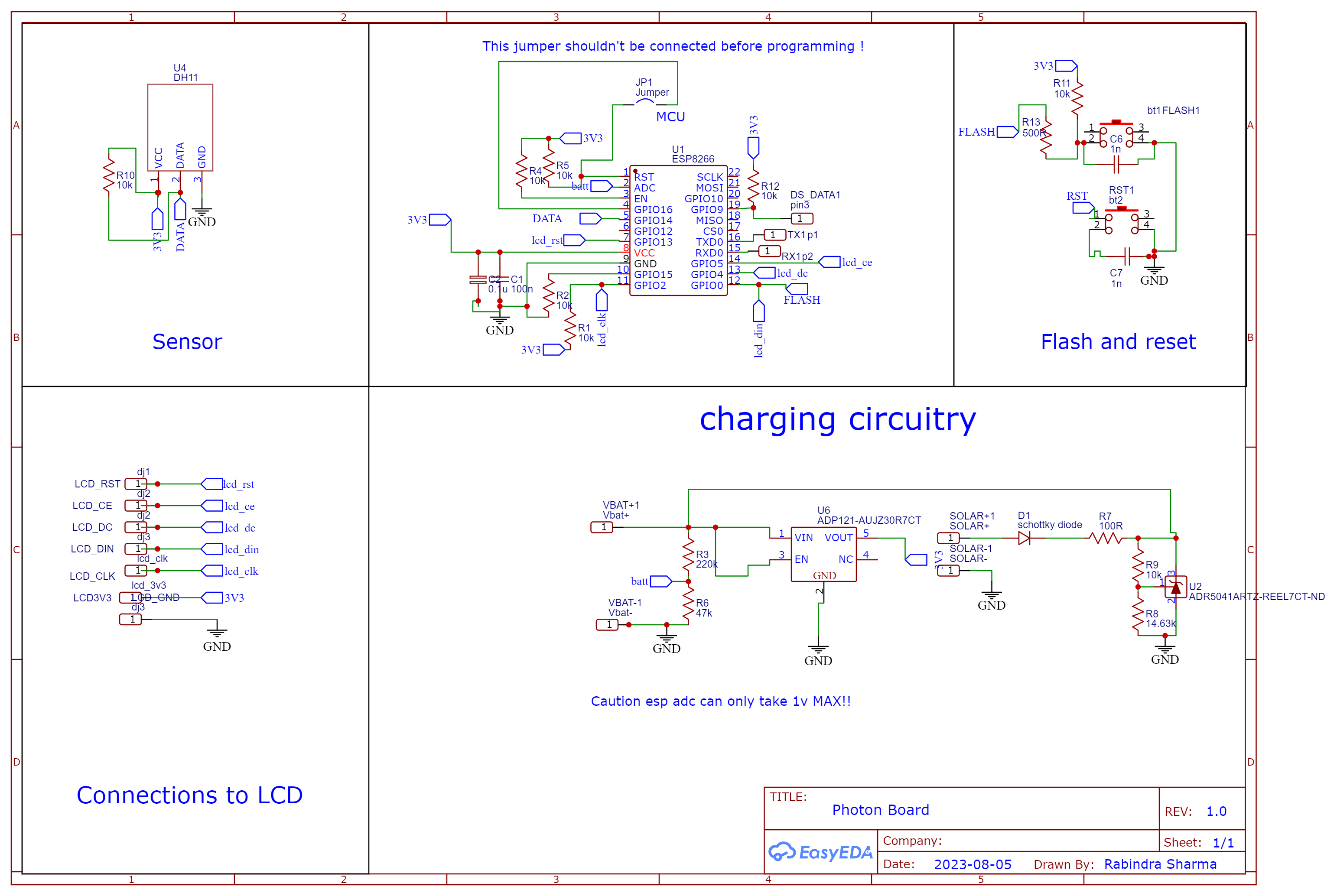
This project is an effort to make a low power microcontroller circuit which is capable of sending data to a remote server, Google in this case, keeping all the power consumption to the lowest, and even have the functionality of showing data using an always on LCD screen. The circuit diagram has been shared, only a single, inexpensive ESP 12F module has been used, along with a solar to power the circuit, although there are several esp boards out there, but this board has a lot of optimisation in power management, the pcb is single sided making it easier to replicate and code open sourced.
Component Choice:
Esp12-F: This is an inexpensive microcontroller with Wi-Fi support and has a couple of breakout pins for io, it has plenty of space for programs in its 4Mib flash and 80 Mhz processor, and a lot of features.
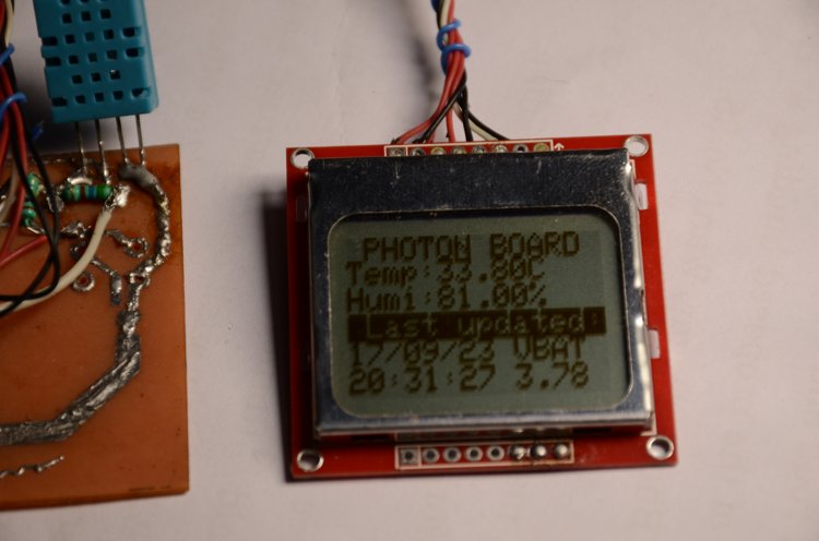
Nokia 5110: This is the display from the old nokia 5110/3110 with Philips pdc8488 controller, this a very low power display and this choice has been made intentionally because of low power consumption, <500uA and because of availability of an onboard ram and doesn't need to be constantly send data to ESP 12F.
Solar panel: a ready-made solar cell of open voltage 6v and short circuit current of 100 mA was used which can provide full charge to a cell in a summer day.
Dht11 : This is a generic and inexpensive, temperature and humidity sensor,
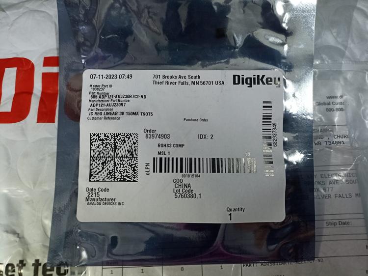
ADP121-AUJZ30R7CT (Analog Devices): This is a 3.3V do, this part was chosen because the battery voltage when discharged reaches lower than 3.7V and conventional linear regulators have a voltage drop of around 1V which is too much because we have very less head room for but this ic can very low voltage drop in range of 200mV. Also we have a lot of head room to work with.
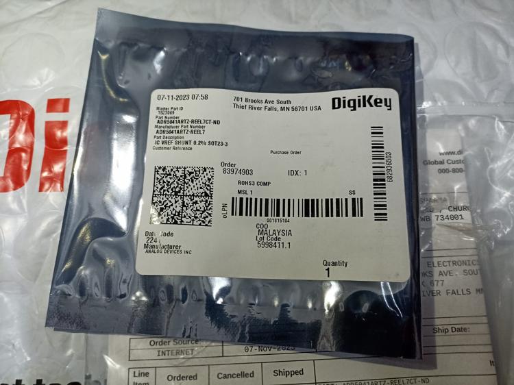
ADR5041ARTZ-REEL7CT-ND (Analog Devices) voltage reference: This is used for line regulation, this is used as a voltage regulator for charging the Li ion cell further detail is discussed later.
Circuit Diagram:
LTSpice Simulation of Charging Circuitry:
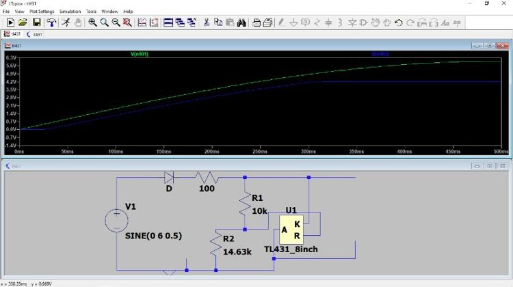
The output voltage is limited to 4.2V and the quiescent current is less than 15uA but since we are using solar this discharge is almost negligible even in cloudy days
PCB for Solar Powered IoT Board
The pcb here is single sided and it was etched using common fecl3,
The pcb was first printed with the image laterally Flipped on a GLOSSY paper (used for photo album printing )and printed using a LASER PRINTER(This is imp other ink types doesn’t work)
Procedure for Preparing the PCB :
- First the copper clad was cut into the desired shape (here 100 X 50mm) and then toner was transferred using cold toner transfer
- Prepare 3:1 mixture of rubbing alcohol to solvent (well you can use spirit and industrial thinner as a replacement) . You need to find the sweet spot and you can go for iron but I don't recommend it because the tracks then when trying to solder they peel off easily.
- Print many copies cause you need to try many times.
- You need to put the mixture on the surface of the cleaned copper clad and then you can place the printed pcb and then you need to wait for all alcohol to evaporate
- Then you can use water to rinse of all the paper and do it gently with running water with fingers
- You can see some places you there are bridges and some traces are not present you can use a needle to remove excess and use a permanent marker for the traces or a whitener, (whitener works better )
After Cold Toner Transfer
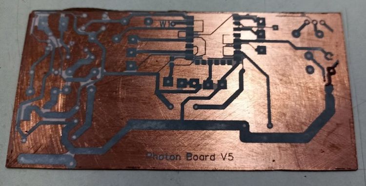
All tracks tinned to prevent corrosion
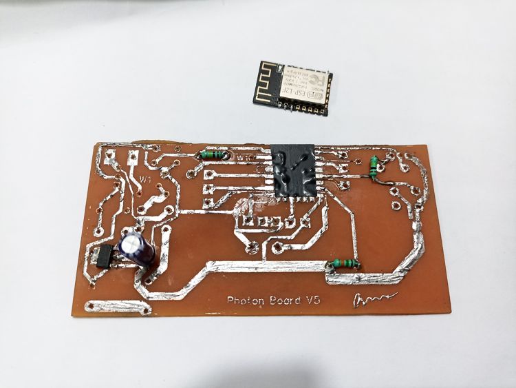
Results of Project
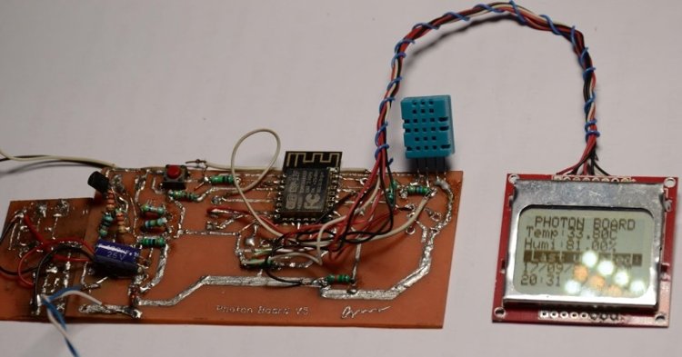
NB: The board left side is the daughter board and its just for new voltage regulator.
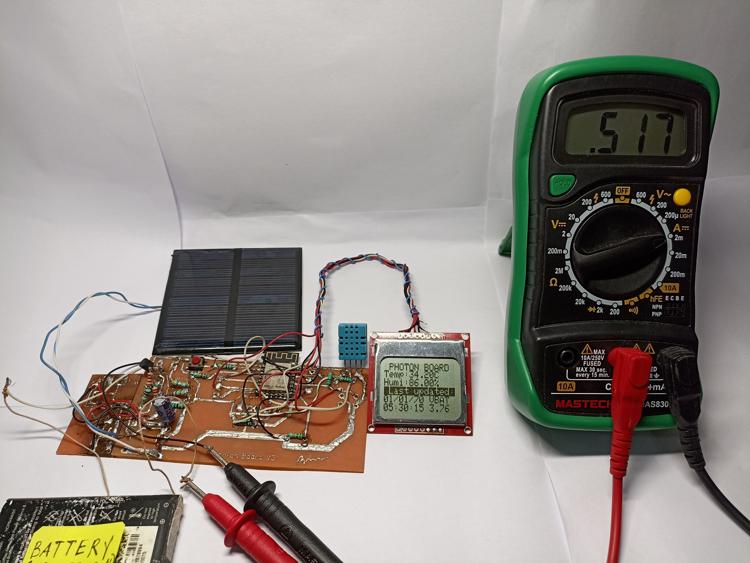
The following picture shows the idle current draw of the system (~520uA)
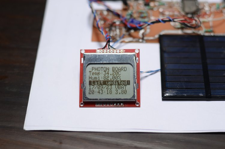
Display running in idle with ~500uA and Current peaks at about 78mA @3.77V Vbat which takes less than 10 sec to update
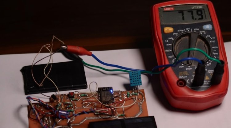
PS:This is a earlier version of the pcb and it used a linear 3.3v regulator and hence i had to add a daughter board for the voltage regulator in my final design but don’t worry this is fixed in the later version of the pcb
Hardware Description:
- The resistor divider can be custom made as per the battery type, here we are using R3 and R6 for setting the divider, here we can have up to 5v for the input and still in code calibration needs to be done, with the multimeter.
- It is recommended to connect lcd after programming if there are any problems while uploading the sketch.
- Nokia5110 display boards needs to be modified and the led power needs to be cut off because the leds in standby consume a lot of current, if you are still facing errors with the display glitching you can open the display frame using a screwdriver and solder the contact pins directly to the pads, cause i’ve had problems and if you are not experienced enough don’t attempt.
- C7 and C8 are debouncing capacitors and these are optional and can be omitted.
- R13 is necessary to protect from overcurrent, as it is an output drive pin.
- There shouldn't be any copper below or above the pcb antennae of esp12f, better to have it hanging outside of the board.
Updates and future scope:
- This project has further scope to be used without the lcd and with an external low power timer chip cutting down the sleep currents to less than 1uA
- Better Solar charging using Mppt charger instead of linear load regulation using a voltage reference
- Upgrading to fastener processor, and having a
Software:
Here are using Arduino ide but you can use avr gcc and simple text editor and get the task done.
Link to my github repo
The working of the code is discussed below -
- First the esp8266 wakes up and tries to connect to the wifi network as specified.
- Next it checks the data from the sensor and then it creates a http post request and send that data along with the adc value (battery voltage)to the google sheets
- The code has an option for checking whether the data was sent correctly and it would try a maximum of 5 times before quitting.
- After successfully posting the data to the server it fetches time and date from a Ntp server
- Eventually the display is updated with the sensor data and date and time of updation and
- The Esp then goes into a deep sleep mode with the time specified (here 30mins) and then when the timer runs outs the esp is reset and the whole cycles repeats.
- The esp is mostly into sleep mode and the whole circuit draws less than 500uA at sleep and during sending data the current draw is ~70mA, which can be fulfilled even indoors with enough lighting.
PS:this program has many other minute features which are not discussed in detail but you can read the code , which is self-explanatory, like getting date time and converting it to string, slicing the string, etc
Here are discussed some parameters about the firmware which needed to be discussed :
Preparing Google Sheets:
- First goto docs.google.com and then create a new sheet and give it a new name and save it.
- Now click on extensions and apps script.
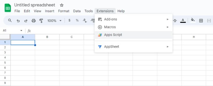
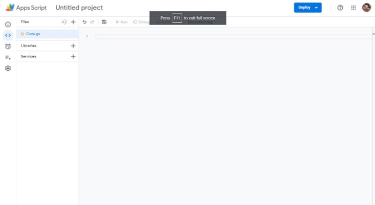
- You will get a screen similar to this, now copy the google script from my repo and paste it, make sure all previous code is deleted, or you can ctrl+a and then ctrl + v
- You will get something like this now
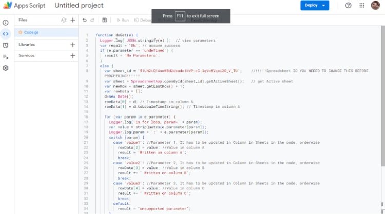
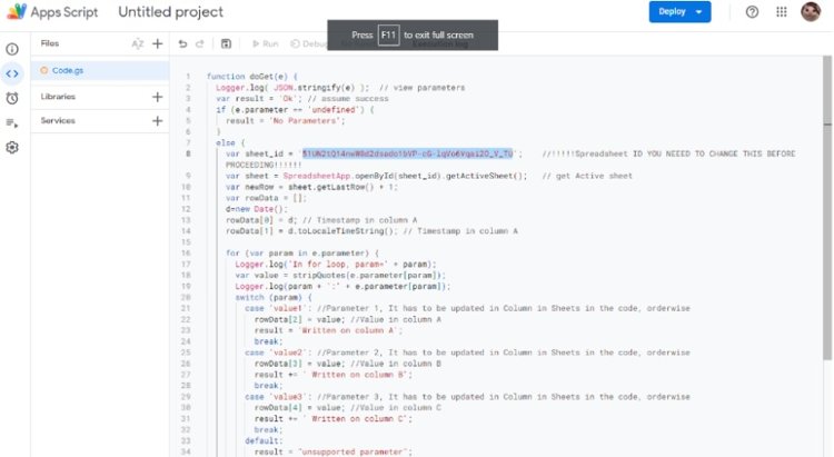
- Now you need to change the sheet ID selected below image
- You can get your sheet id from the google sheets itself, watch below:

- Paste the sheets id into the Google scripts.
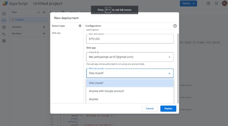
- Now click on deploy> new deployment and then select the gear icon and select web app
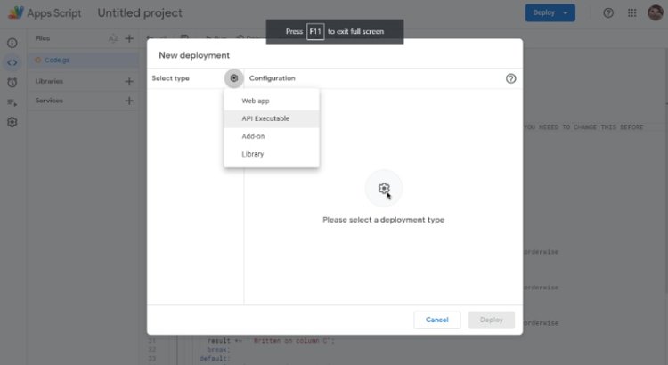
- Click on who has access and then select anyone with the link and click deploy.
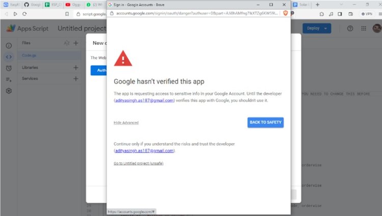
- Authorize and goto advanced and click on the link and give permissions and don’t worry this permission is only for the google sheets and nothing else
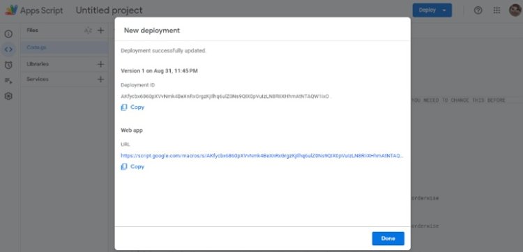
- After successful deployment you would get a screen like this, the first one is your GAS ID, save these details as you would need it for future purpose.
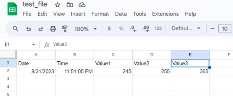
- Testing without ESP, well its possible to test with within a browser now copy the URL above and paste it into the browser and add this at the end without quotes
- “?value1=245&value2=255&value3=256” and hit enter

- Now if everything workshop well then you would see a screen like this, which suggests that the back end is working properly now we need to look at the code for esp.

Programming the Esp
We will be using a usb to TTLl converter for this purpose, but just keep in mind that we are gonna program using manual mode and in this mode the we need to manually press flash and reset buttons in order to reset .
NB:use only TTL converters with 3.3V logic and you can even use arduino to program but this is out of scope of this tutorial but it is reall doable.
Before uploading the code you would need to install certain libraries listed below:
This is the adafruit library for Nokia 5110 display module
This library is used since the conventional library poses some problem with esp boards, this works well
Using to fetch time for updating the display
Also do remember to install the esp core for arduino before proceeding, its pretty simple because I already have a tutorial on how to install esp core on arduino.
You need to select the board to( NODE MCU 1.0 ESP12E)
Don’t worry esp12F and esp12E are are almost same boards with esp12f just having an antenna upgrade . And if you are facing issues regarding slow upload times then you can upload speed to 91600, (i've tested it with 1.5m usb cable with 20cm tx rx cables)
Getting the board into programming mode:
Well i like to program the board in this way :
- Fist i’d compile the code first to check whether its working fine or not
- Then i would hold the the flash button and press the reset button momentarily till the led blinks once
- Now I would upload the code and after the code is uploaded we need to again push the reset button
- While programming the arduino terminal would show percentages and memory address written to and the the board led would blink
Warning! Do not connect gpio 16 with RST ( i.e JP1) before programming as it may cause errors while uploading the sketch !
Now for minimal use the following data must be changed :
The wifi credentials and the gas ID needs to be modified
const char* ssid = "Note 10s"; //--> Your wifi name or SSID.
const char* password = "abcd1234"; //--> Your wifi password.
//----------------------------------------Host & httpsPort
const char* host = "script.google.com";
const int httpsPort = 443;
//----------------------------------------

WiFiClientSecure client; //--> Create a WiFiClientSecure object.

String GAS_ID = "AKfycbwkAkxc0mx2mY5fZGTYZqjRlnGIMhAG1UOj9BauQ7ZMY5JvTrA0jqt937Fq7-cG2KJ1_g"; //--> when you succesfulyl deploy you would get a link and in that link after script.google.com and beofre execute/ is your gasid
You can also change other parameters for this code:
1. Send interval which is governed by the variable
unsigned long sleep_time = 1800e6 Change only 1800 to whatever time you want in seconds.
Eg. for 100 sec interval the code needs to e modified like
unsigned long sleep_time = 100e6
2. Changing the contrast for the display
int contrastValue = 60; Change this from 0-100 for contrast of your choice and changing contrast has no effect on current consumption
3. GMT Correction, you need to change the selected value and convert the gmt of your area into seconds and plug it here
String TIME() {
  unsigned long epochTime = timeClient.getEpochTime() + 19800;

  unsigned long days = epochTime / 86400;
  unsigned long seconds = epochTime % 86400;

  unsigned int hours = seconds / 3600  ;
  seconds %= 3600;
  unsigned int minutes = seconds / 60  ;
  seconds %= 60;

  unsigned int year = 1970;
  while (days >= 365) {
    if (year % 4 == 0 && (year % 100 != 0 || year % 400 == 0)) {
      if (days >= 366) {
        days -= 366;
        year++;
      } else {
        break;
      }
    } else {
      days -= 365;
      year++;
    }
  }
Eg.
If your area has GMT of +5:30 then the factor would be + ( 5*60 + 30 ) * 60
And if it's -5:30 then the factor would be +( 5*60 + 30 ) * 60
It's pretty simple
4. ADC : the adc is connected to the battery via a resistor divider network and can have a maximum of 5V with this network configuration, and remember not to put more than 1V into ADC.
Troubleshooting
Well it's pretty much sure that your circuit is not working in the first go so, as per the saying "If your circuit works in the first go you're lucky", so I'm classifying the problems into parts here.
1. Google sheets not working : well make sure you have run the code in the Google scripts after deployment. Well you can check whether it's working or not using a browser.
2. Unable to program ESP: it's showing error codes or garbage in serial monitor, well if this happens you first need to change the baud rate to 78600 and then check the monitor whether you are getting reset codes, and check which mode you are and which pins are not connected. This is a great tutorial on reset modes and boot codes by tiktronics.
3. Charging current is too low, the resistor R7 should be reduced to lower values, ideally it is set to 100mA but in reality it doesn't work and needs fine tuning and it can be as low as 5-10 ohms, but since the li ion battery is very sensitive to overvoltages, the regulation circuitry is necessary.
4. Well if you have no idea where to start when troubleshooting, then first try to upload the blink sketch to check whether the eps is working or not, then we move on to the voltages and before soldering the esp solder the power components and check whether it is working or not, then move on to upload the sample stretch for the DHT and check whether it is working or not and if you wish to use other pins remember that gpio16 can’t be used as it is used for the purpose of wake up and there are several limitations for the gpio used.
I’ve tried to avoid all errors while writing this, but i'm open to constructive suggestions, you can write me at
[email protected]
Complete Project Code
#include <SPI.h>

#include <Adafruit_GFX.h>

#include <Adafruit_PCD8544.h>

#include "DHTesp.h"

#include <NTPClient.h>

#ifdef ESP32

#pragma message(THIS EXAMPLE IS FOR ESP8266 ONLY!)

#error Select ESP8266 board.

#endif
#include <ESP8266WiFi.h>

#include <WiFiClientSecure.h>

#include <WiFiUdp.h>
#include "DHT.h"

#define ON_Board_LED 2

#define dht_pin 14
WiFiUDP ntpUDP;

NTPClient timeClient(ntpUDP);
unsigned long currentTime ;

unsigned long sleep_time = 1800e6 ; // here change the 1800e6 represents the amount of seconds the board woudl be in sleep , here its 1800secs
const float CF          = 6.59e-3 ; //This is the correction factor for

const int analogInPin = A0 ;
float h;          //first  variable send to the google sheets  , you can change this to send anything else

float t;          //second variable send to the google sheets

float bat = 0  ;  //Third  variabel send to the google sheets

String sheetHumid = "";

String sheetTemp  = "";

String sheetbatt  = "";

bool flag = 0 ;
const char* ssid = "Note 10s"; //--> Your wifi name or SSID.

const char* password = "abcd1234"; //--> Your wifi password.

//----------------------------------------Host & httpsPort

const char* host = "script.google.com";

const int httpsPort = 443;

//----------------------------------------
WiFiClientSecure client; //--> Create a WiFiClientSecure object.
String GAS_ID = "AKfycbwkAkxc0mx2mY5fZGTYZqjRlnGIMhAG1UOj9BauQ7ZMY5JvTrA0jqt937Fq7-cG2KJ1_g"; //--> when you succesfulyl deploy you would get a link and in that link after script.google.com and beofre execute/ is your gasid
DHTesp dht;

/* Declare LCD object for SPI

  Adafruit_PCD8544(CLK,DIN,D/C,CE,RST);*/

Adafruit_PCD8544 display = Adafruit_PCD8544(D4, D3, D2, D1, D7); /*  equiv to gpios 2,0,4,5,13 */

int contrastValue = 60; /* Default Contrast Value */

void setup()

{

  if(((analogRead(analogInPin)  * CF )  ) < 3.3 ){

    ESP.deepSleep(0);


    }

  Serial.begin(115200);
  dht.setup(dht_pin, DHTesp::DHT11);
  h = dht.getHumidity();                                              // Reading temperature or humidity takes about 250 milliseconds!

  t = dht.getTemperature();

  bat = (analogRead(analogInPin)  * CF ) ;

  const char* ntpServerName = "pool.ntp.org";

  const int ntpServerPort = 123;

  WiFiUDP ntpUDP;

  NTPClient timeClient(ntpUDP, ntpServerName, ntpServerPort);

  display.begin();
  /* Change the contrast using the following API*/

  display.setContrast(contrastValue);
  /* Clear the buffer */

  display.clearDisplay();

  display.display();

  delay(100);
  /* Now let us display some text */

  display.setTextColor(WHITE,BLACK);


  display.setCursor(0, 0);

  display.println(" PHOTON BOARD");

   display.setTextColor(BLACK);

  display.setCursor(8, 10);

  display.println("UPDATING..");
  display.display();

  delay(20);

  WiFi.begin(ssid, password); //--> Connect to your WiFi router

  Serial.println("");
  pinMode(2 , OUTPUT); //--> On Board LED port Direction output

  digitalWrite(2, HIGH); //--> Turn off Led On Board
  //----------------------------------------Wait for connection

  Serial.print("Connecting");

  while (WiFi.status() != WL_CONNECTED) {

    Serial.print(".");

    //----------------------------------------Make the On Board Flashing LED on the process of connecting to the wifi router.

    digitalWrite(2, HIGH );

    delay(250);

    digitalWrite(2, LOW);

    delay(25);

    //----------------------------------------

  }

  //----------------------------------------

  digitalWrite(2, HIGH); //--> Turn off the On Board LED when it is connected to the wifi router.

  if (Serial.available() == 1) {

    Serial.println("");

    Serial.print("Successfully connected to : ");

    Serial.println(ssid);

    Serial.print("IP address: ");

    Serial.println(WiFi.localIP());

    Serial.println();
  }

  //----------------------------------------
  client.setInsecure();

  timeClient.begin();

}
void st_cloud() {
  Serial.println("==========");

  Serial.print("connecting to ");

  Serial.println(host);
  //----------------------------------------Connect to Google host

  if (!client.connect(host, httpsPort)) {

    Serial.println("connection failed");

    return;

  }

  //----------------------------------------
  //----------------------------------------Processing data and sending data

  String string_temperature =  String(t);

  // String string_temperature =  String(tem, DEC);

  String string_humidity =  String(h);

  String string_batt =  String(bat) + "V";
  // retrying if the data is not posted to the server , maybe it failed on first try at max we try 5 times

  unsigned int counter = 0 ;

  while (flag == 0 ) {
    String url = "/macros/s/" + GAS_ID + "/exec?value1=" + string_temperature + "&value2=" + string_humidity + "&value3=" + string_batt  ;

    Serial.print("requesting URL: ");

    Serial.println(url);
    client.print(String("GET ") + url + " HTTP/1.1\r\n" +

                 "Host: " + host + "\r\n" +

                 "User-Agent: BuildFailureDetectorESP8266\r\n" +

                 "Connection: close\r\n\r\n");
    Serial.println("request sent");

    //----------------------------------------
    //----------------------------------------Checking whether the data was sent successfully or not

    update_display();

    while (client.connected()) {

      String line = client.readStringUntil('\n');

      if (line == "\r") {

        Serial.println("headers received");

        break;

      }

    }

    String line = client.readStringUntil('\n');

    if (line.startsWith("Content-Type")) {

      Serial.println("esp8266/Arduino CI successfull!");

      flag = 1 ;

    } else {

      Serial.println("esp8266/Arduino CI has failed");

      flag = 0 ;

    }

    Serial.print("reply was : ");

    Serial.println(line);

    Serial.println("closing connection");

    Serial.println("==========");

    Serial.println();

    if (counter == 5 ) {
      break ;

    }

    counter = counter + 1 ;

    if(counter == 5 ){

      break ;

      }
  }
  timeClient.update();
}

String TIME() {

  unsigned long epochTime = timeClient.getEpochTime() + 19800;
  unsigned long days = epochTime / 86400;

  unsigned long seconds = epochTime % 86400;
  unsigned int hours = seconds / 3600  ;

  seconds %= 3600;

  unsigned int minutes = seconds / 60  ;

  seconds %= 60;
  unsigned int year = 1970;

  while (days >= 365) {

    if (year % 4 == 0 && (year % 100 != 0 || year % 400 == 0)) {

      if (days >= 366) {

        days -= 366;

        year++;

      } else {

        break;

      }

    } else {

      days -= 365;

      year++;

    }

  }
  unsigned char monthTable[12] = {31, 28, 31, 30, 31, 30, 31, 31, 30, 31, 30, 31};

  unsigned int month = 0;

  while (days >= monthTable[month]) {

    if (month == 1 && (year % 4 == 0 && (year % 100 != 0 || year % 400 == 0))) {

      if (days >= 29) {

        days -= 29;

        month++;

      } else {

        break;

      }

    } else {

      days -= monthTable[month];

      month++;

    }

  }
  unsigned int day = days + 1;
  char buffer[20];

  sprintf(buffer, "%02u/%02u/%02u %02u:%02u:%02u", day, month + 1, year % 100, hours, minutes, seconds);

  return String(buffer);

}
void update_display() {
  display.clearDisplay();

  display.setCursor(0, 0);


  display.print(" PHOTON BOARD");


  display.setCursor(0, 7);

  display.print("Temp:");

  display.print(t);

  display.print("C");
  display.setCursor(0, 15);

  display.print("Humi:");

  display.print(h);

  display.print("%");
  display.setCursor(0, 23);

  display.setTextColor(WHITE,BLACK);

  display.print(" Last updated:");

  display.setTextColor(BLACK);

  display.setCursor(0, 31);

  display.print(TIME().substring(0, 8));

  display.print(" VBAT");

  display.setCursor(0, 39);

  display.print(TIME().substring(9, 17));

  display.print(" ");
  display.print(bat,2);

  display.display();

}
void loop() {


  delay(100) ;


  h = dht.getHumidity();

  t = dht.getTemperature();
  st_cloud();

  update_display();

  ESP.deepSleep(sleep_time);

}

