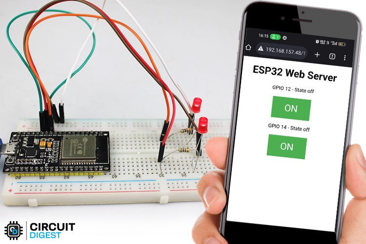
What is an ESP32 Web Server?
In the Internet, all the websites are hosted on a computer and this computer is called a server. Since this particular server is used to serve web pages and web requests, we call it a web server. Instead of using a computer, we can also use an ESP32 to respond to web requests, thanks to the ESP32’s built-in WiFi. The ESP32 can not only respond to requests, but also serve small web pages, that were either hard coded to the code or stored in flash storage of an SD card.
In this blog post, we'll explore how to build an ESP32 LED web server from scratch. We'll go through the steps of setting up the ESP32, connecting the LEDs, and creating a web interface to control them. Whether you're a seasoned maker or just starting out with IoT projects, this tutorial will help you take your skills to the next level.
You can also take a look at a few other ESP32 Projects that we made and also check our previously built webservers using Raspberry Pi, NodeMCU and other microcontrollers:
- How to Build NodeMCU Webserver and control an LED from a Webpage
- Getting started with Node.js and Raspberry Pi: Controlling an LED with Node.js Webserver
- AJAX with ESP8266: Dynamic Web Page Update Without Reloading
- Connecting ESP8266 with STM32F103C8: Creating a Webserver
- ESP8266 Interfacing with ARM7-LPC2148- Creating a Webserver to control an LED
Now, Let’s get a brief idea lets lern how to make an LED On/Off using ESP32 Webserver
- Connecting LEDs on GPIO12 and GPIO14 on ESP32 so that you can control them
- After the coding is done. Try to access the control webpage by inputting the IP address of esp32 in the browser
- Clicking the buttons on the webpage to turn the LED “ON” or “OFF”
Materials Required to Build a LED Control Webserver using ESP32
The components we require to make this project are: -
- ESP32 Development Board - this is the main component that will be used to control the LED lights through the webserver.
- LED Lights - you can use any type of LED depending on your project requirements. We have used 2x 5mm LEDs for this project.
- Breadboard - this will be used to connect the LED lights to the ESP32 microcontroller.
- Jumper wires - these will be used to connect the breadboard to the ESP32 microcontroller and the LED lights.
- USB Cable - to connect the ESP32 Development Board to your computer for programming.
- Computer - to program and upload the code to the ESP32 Development Board.
- Resistor - to limit the current going through the LED lights and prevent them from burning out.
Working of ESP32 LED WebServer
The project works by creating a web server on the ESP32 microcontroller that serves a web page to a client device, such as a computer or mobile phone, over Wi-Fi. The web page contains controls that allow you to turn the LED lights on or off.
Here's a step-by-step breakdown of how the ESP32 LED webserver project works:
- The ESP32 microcontroller is connected to the LED lights and programmed to serve as a web server.
- The web server code is uploaded to the ESP32 using the Arduino IDE or other programming tools.
- The ESP32 is connected to a Wi-Fi network, allowing it to communicate with client devices over the network.
- When a client device connects to the ESP32's IP address, the web server code serves a web page to the client device's web browser.
- The web page contains controls for the LED lights, allowing the user to turn them on or off.
- When the user interacts with the controls on the web page, the ESP32 microcontroller receives the command and adjusts the LED lights accordingly.
- The ESP32 sends a response back to the client device, updating the web page with the current state of the LED lights.
Circuit Diagram of ESP32 LED WebServer
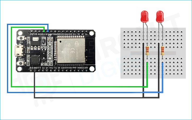
Below is the circuit diagram to control an LED using ESP32 based webserver:
The ESP32 microcontroller has many GPIO pins that can be used for interfacing with external devices, such as LED lights. In this example, we will interface the ESP32 with two LED lights connected to GPIO pins 12 and 14.
Here's how to interface the ESP32 with two LED lights:
Connect one end of a 220-ohm resistor to GPIO pin 12 on the ESP32, and connect the other end of the resistor to the positive (anode) leg of one LED light.
Connect the negative (cathode) leg of the LED light to the ground (GND) on the ESP32.
Repeat steps 1 and 2 for GPIO pin 14 and the other LED light.
You can also use the ESP32 Ethernet webserver for the same, in which case you will need an ethernet shield for ESP32 board and minor changes with the code.
Installing the ESP32 board on the Arduino IDE
The Arduino IDE provides a user-friendly interface for beginners and advanced users alike, allowing you to write and upload code to the ESP32 without requiring advanced knowledge of programming languages.
Here’s an in-depth tutorial that you can follow for this - Getting Started with ESP32 using Arduino IDE - Blink LED
You don’t need to install any specific library to use the web server since the ESP32 webserver library is a part of ESP32 Arduino core. There are many ESP32 webserver examples that come with the library and you may check them out too. The ESP32 webserver button example below lets you control two LEDs using the ESP32 via a smartphone or a computer.
Code to build your own ESP32Webserver
Before Uploading the code. Make sure you change the network credentials in the code to your SSID and password in this section.
const char* ssid = " REPLACE_WITH_YOUR_SSID";
const char* password = " REPLACE_WITH_YOUR_PASSWORD";
Complete code of ESP32 LED Webserver
// Load Wi-Fi library
#include <WiFi.h>
// Replace with your network credentials
const char* ssid = " REPLACE_WITH_YOUR_SSID";
const char* password = " REPLACE_WITH_YOUR_PASSWORD";
// Set web server port number to 80
WiFiServer server(80);
// Variable to store the HTTP request
String header;
// Auxiliary variables to store the current output state
String output12State = "off";
String output14State = "off";
// Assign output variables to GPIO pins
const int output12 = 12;
const int output14 = 14;
// Current time
unsigned long currentTime = millis();
// Previous time
unsigned long previousTime = 0;
// Define timeout time in milliseconds (example: 2000ms = 2s)
const long timeoutTime = 2000;
void setup() {
  Serial.begin(115200);
  // Initialize the output variables as outputs
  pinMode(output12, OUTPUT);
  pinMode(output14, OUTPUT);
  // Set outputs to LOW
  digitalWrite(output12, LOW);
  digitalWrite(output14, LOW);
  // Connect to Wi-Fi network with SSID and password
  Serial.print("Connecting to ");
  Serial.println(ssid);
  WiFi.begin(ssid, password);
  while (WiFi.status() != WL_CONNECTED) {
    delay(500);
    Serial.print(".");
  }
  // Print local IP address and start web server
  Serial.println("");
  Serial.println("WiFi connected.");
  Serial.println("IP address: ");
  Serial.println(WiFi.localIP());
  server.begin();
}
void loop(){
  WiFiClient client = server.available();   // Listen for incoming clients
  if (client) {                             // If a new client connects,
    currentTime = millis();
    previousTime = currentTime;
    Serial.println("New Client.");          // print a message out in the serial port
    String currentLine = "";                // make a String to hold incoming data from the client
    while (client.connected() && currentTime - previousTime <= timeoutTime) {  // loop while the client's connected
      currentTime = millis();
      if (client.available()) {             // if there's bytes to read from the client,
        char c = client.read();             // read a byte, then
        Serial.write(c);                    // print it out the serial monitor
        header += c;
        if (c == '\n') {                    // if the byte is a newline character
          // if the current line is blank, you got two newline characters in a row.
          // that's the end of the client HTTP request, so send a response:
          if (currentLine.length() == 0) {
            // HTTP headers always start with a response code (e.g. HTTP/1.1 200 OK)
            // and a content-type so the client knows what's coming, then a blank line:
            client.println("HTTP/1.1 200 OK");
            client.println("Content-type:text/html");
            client.println("Connection: close");
            client.println();
            // turns the GPIOs on and off
            if (header.indexOf("GET /12/on") >= 0) {
              Serial.println("GPIO 12 on");
              output12State = "on";
              digitalWrite(output12, HIGH);
            } else if (header.indexOf("GET /12/off") >= 0) {
              Serial.println("GPIO 12 off");
              output12State = "off";
              digitalWrite(output12, LOW);
            } else if (header.indexOf("GET /14/on") >= 0) {
              Serial.println("GPIO 14 on");
              output14State = "on";
              digitalWrite(output14, HIGH);
            } else if (header.indexOf("GET /14/off") >= 0) {
              Serial.println("GPIO 14 off");
              output14State = "off";
              digitalWrite(output14, LOW);
            }
            // Display the HTML web page
            client.println("<!DOCTYPE html><html>");
            client.println("<head><meta name=\"viewport\" content=\"width=device-width, initial-scale=1\">");
            client.println("<link rel=\"icon\" href=\"data:,\">");
            // CSS to style the on/off buttons
            // Feel free to change the background-color and font-size attributes to fit your preferences
            client.println("<style>html { font-family: Helvetica; display: inline-block; margin: 0px auto; text-align: center;}");
            client.println(".button { background-color: #4CAF50; border: none; color: white; padding: 16px 40px;");
            client.println("text-decoration: none; font-size: 30px; margin: 2px; cursor: pointer;}");
            client.println(".button2 {background-color: #555555;}</style></head>");
            // Web Page Heading
            client.println("<body><h1>ESP32 Web Server</h1>");
            // Display current state, and ON/OFF buttons for GPIO 12
            client.println("<p>GPIO 12 - State " + output12State + "</p>");
            // If the output12State is off, it displays the ON button
            if (output12State=="off") {
              client.println("<p><a href=\"/12/on\"><button class=\"button\">ON</button></a></p>");
            } else {
              client.println("<p><a href=\"/12/off\"><button class=\"button button2\">OFF</button></a></p>");
            }
            // Display current state, and ON/OFF buttons for GPIO 14
            client.println("<p>GPIO 14 - State " + output14State + "</p>");
            // If the output14State is off, it displays the ON button
            if (output14State=="off") {
              client.println("<p><a href=\"/14/on\"><button class=\"button\">ON</button></a></p>");
            } else {
              client.println("<p><a href=\"/14/off\"><button class=\"button button2\">OFF</button></a></p>");
            }
            client.println("</body></html>");
            // The HTTP response ends with another blank line
            client.println();
            // Break out of the while loop
            break;
          } else { // if you got a newline, then clear currentLine
            currentLine = "";
          }
        } else if (c != '\r') {  // if you got anything else but a carriage return character,
          currentLine += c;      // add it to the end of the currentLine
        }
      }
    }
    // Clear the header variable
    header = "";
    // Close the connection
    client.stop();
    Serial.println("Client disconnected.");
    Serial.println("");
  }
}
Uploading the code on the ESP32 board
To upload code to an ESP32 board, you'll need to follow these steps:
- Connect your ESP32 board to your computer using a USB cable.
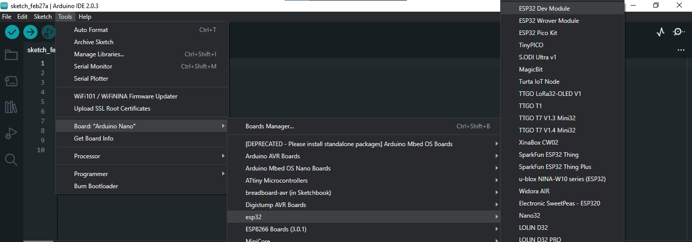
- Open the Arduino IDE and go to "Tools" > "Board" and select your ESP32 board from the list.
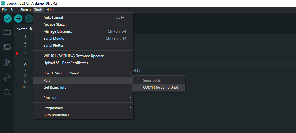
- Make sure to also select the correct port under "Tools" > "Port".
- Write or copy your code into the Arduino IDE.
- Verify that your code compiles by clicking the "Verify" button (checkmark icon) in the top-left corner of the IDE. If there are any errors, fix them before proceeding.
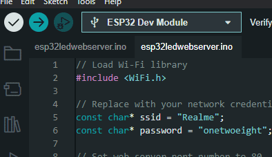
- Upload your code to the ESP32 board by clicking the "Upload" button (right arrow icon) in the top-left corner of the IDE. The IDE will compile your code and then upload it to the ESP32 board. The progress of the upload will be shown in the bottom of the IDE.
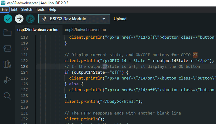
Once the upload is complete, the ESP32 board will automatically reset and start running your code.
Note: Before uploading the code, you may need to press the "Boot" or "Reset" button on the ESP32 board to enter the bootloader mode. The specific steps for entering the bootloader mode may vary depending on your ESP32 board. Refer to the documentation for your board to learn how to do this.
Finding the IP address of the ESP32 board
- Open the Serial Monitor in the Arduino IDE by clicking on the magnifying glass icon in the top right corner of the IDE window.
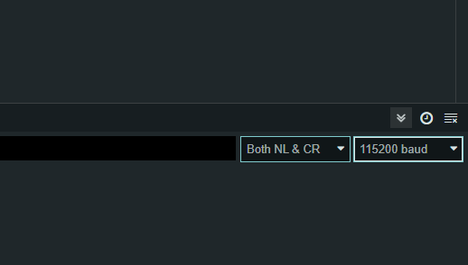
- Select a baud rate of 115200 from the dropdown list in the bottom right corner of the Serial Monitor window.
- Reset the ESP32 board by pressing the EN(RST) button on the board.
- Wait for the ESP32 board to connect to the WiFi network. The Serial Monitor will display messages that indicate the progress of the connection.

- Once the ESP32 board is connected to the WiFi network, it will obtain an IP address from the network. The Serial Monitor will display the IP address of the ESP32 board.

Alternatively, you can use a network scanning tool such as "Advanced IP Scanner" to scan your network for connected devices and identify the IP address of your ESP32 board.
Connecting to the ESP32 Webserver and testing it
- Open the same network through a device or use the same device to whose hotspot your ESP32 is connected
- Open a web browser on your computer or mobile device and enter the IP address of the ESP32 board into the address bar.
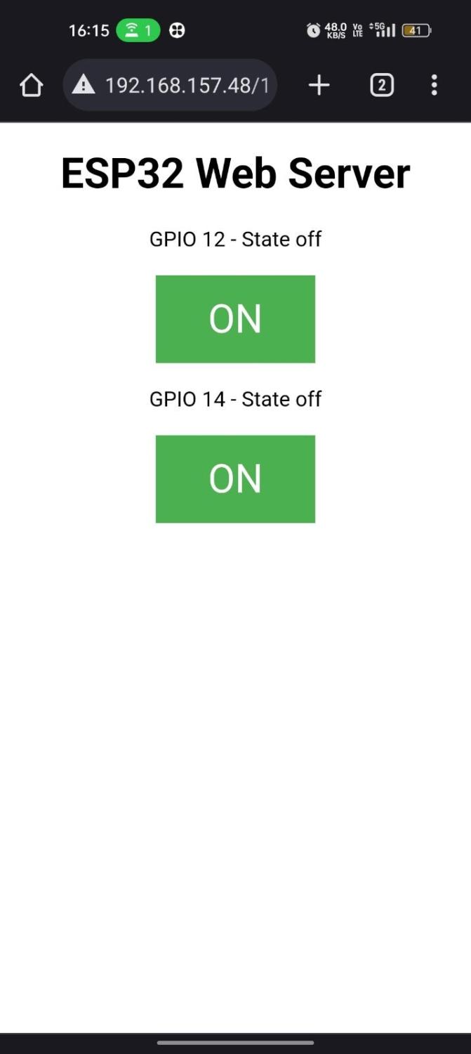
If you take a closer look, you will find additional data on the Serial monitor. you can get more details about the webserver you are accessing like HTTP requests, host address etc.
After you’ve accessed the control page on your browser you can test it by clicking “ON” and “OFF” and checking the LED state and serial monitor simultaneously
Now if you click on the GPIO 12 button, you will see that the serial monitor gets a request on 12/on URL and then your led lights up.

After this is done, the Esp32 updates its state on the webpage as “ON” or “OFF”.
This will work the same for GPIO 14 too.
Explanation of Code of ESP32 LED Webserver
#include <WiFi.h>
This line includes the header file for the WiFi library, which is used to connect to a Wi-Fi network and communicate with other devices over the network.
// Replace with your network credentials
const char* ssid = "Replace with your SSID";
const char* password = "Replace with your password";
These lines define the SSID and password of the Wi-Fi network that the ESP32 board will connect to. You should replace these values with the SSID and password of your own network.
WiFiServer server(80);
This line creates a server object that will listen for incoming HTTP requests on port 80. Port 80 is the default port for HTTP traffic.
String header;
This line defines a String variable called "header" that will be used to store the HTTP request received from a client.
// Auxiliar variables to store the current output state
String output12State = "off";
String output14State = "off";
These lines define two String variables called "output12State" and "output14State" that will be used to store the current state (on or off) of two output pins on the ESP32 board.
// Assign output variables to GPIO pins
const int output12 = 12;
const int output14 = 14;
These lines define two constants called "output12" and "output14" that represent the GPIO pins on the ESP32 board that will be used to control the state of external devices.
// Current time
unsigned long currentTime = millis();
// Previous time
unsigned long previousTime = 0;
// Define timeout time in milliseconds (example: 2000ms = 2s)
const long timeoutTime = 2000;
These three lines create variables to measure the time that has elapsed since the server started running, and to set a timeout for client requests.
void setup() {
  Serial.begin(115200);
  // Initialize the output variables as outputs
  pinMode(output12, OUTPUT);
  pinMode(output14, OUTPUT);
  // Set outputs to LOW
  digitalWrite(output12, LOW);
  digitalWrite(output14, LOW);
  // Connect to Wi-Fi network with SSID and password
  Serial.print("Connecting to ");
  Serial.println(ssid);
  WiFi.begin(ssid, password);
  while (WiFi.status() != WL_CONNECTED) {
    delay(500);
    Serial.print(".");
  }
  // Print local IP address and start web server
  Serial.println("");
  Serial.println("WiFi connected.");
  Serial.println("IP address: ");
  Serial.println(WiFi.localIP());
  server.begin();
}
This is the setup() function, which is called once when the ESP32 starts up. It sets the Serial communication speed, initializes the two GPIO pins as outputs and sets them to LOW. It then connects to the WiFi network using the SSID and password previously defined, and waits until it is connected. Once it's connected, it prints the IP address of the ESP32 in the serial monitor, and starts the web server.
void loop(){
This is the main loop function that runs repeatedly while the ESP32 is powered on.
WiFiClient client = server.available(); // Listen for incoming client
This line listens for incoming client connections to the ESP32 web server. If there is a client available, it creates a new instance of the WiFiClient class and assigns it to the client variable.
if (client) {
This checks if a new client has connected to the web server. If a client has connected, the code inside the if statement will execute.
currentTime = millis();
    previousTime = currentTime;
These two lines get the current time in milliseconds and assign it to both the currentTime and previousTime variables.
Serial.println("New Client.");
This line prints a message to the serial monitor indicating that a new client has connected.
String currentLine = "";
This line creates an empty string variable named currentLine which will hold incoming data from the client.
    while (client.connected() && currentTime - previousTime <= timeoutTime) {  // loop while the client's connected

      currentTime = millis();
This while loop runs as long as the client is connected and the elapsed time since the previous loop iteration is less than or equal to the timeoutTime variable.
  if (client.available()) {             // if there's bytes to read from the client,
        char c = client.read();             // read a byte, then
        Serial.write(c);                    // print it out the serial monitor
        header += c;
This block of code checks if there is data available to read from the client. If there is data available, it reads a byte from the client, prints it to the serial monitor, and appends it to the header variable.
   if (c == '\n') {                    // if the byte is a newline character
          // if the current line is blank, you got two newline characters in a row.
          // that's the end of the client HTTP request, so send a response:
          if (currentLine.length() == 0) {
This code checks if the current character is a newline character (\n). If it is, it checks if the current line is blank. If it is, it means that the end of the HTTP request has been reached, and the ESP32 should send a response to the client.
// HTTP headers always start with a response code (e.g. HTTP/1.1 200 OK)
            // and a content-type so the client knows what's coming, then a blank line:
            client.println("HTTP/1.1 200 OK");
            client.println("Content-type:text/html");
            client.println("Connection: close");
            client.println();
This code sends HTTP headers to the client indicating that the response is an HTML page.
 // turns the GPIOs on and off
            if (header.indexOf("GET /12/on") >= 0) {
              Serial.println("GPIO 12 on");
              output12State = "on";
              digitalWrite(output12, HIGH);
            } else if (header.indexOf("GET /12/off") >= 0) {
              Serial.println("GPIO 12 off");
              output12State = "off";
              digitalWrite(output12, LOW);
            } else if (header.indexOf("GET /14/on") >= 0) {
              Serial.println("GPIO 14 on");
              output14State = "on";
              digitalWrite(output14, HIGH);
            } else if (header.indexOf("GET /14/off") >= 0) {
              Serial.println("GPIO 14 off");
              output14State = "off";
              digitalWrite(output14, LOW);
            }
This code is handling HTTP GET requests received by the server, and based on the request it is turning GPIO pins on or off.
Explanation of the HTML of ESP32 Led Webserver
client.println("<!DOCTYPE html><html>");
client.println("<head><meta name=\"viewport\" content=\"width=device-width, initial-scale=1\">");
client.println("<link rel=\"icon\" href=\"data:,\">");
These lines create the HTML header of the web page, including the viewport meta tag and an empty favicon link.
client.println("<style>html { font-family: Helvetica; display: inline-block; margin: 0px auto; text-align: center;}");
client.println(".button { background-color: #4CAF50; border: none; color: white; padding: 16px 40px;");
client.println("text-decoration: none; font-size: 30px; margin: 2px; cursor: pointer;}");
client.println(".button2 {background-color: #555555;}</style></head>");
This block of code defines the CSS styles that will be applied to the buttons in the web page.
client.println("<body><h1>ESP32 Web Server</h1>");
This line sets the main heading of the web page.
client.println("<p>GPIO 12 - State " + output12State + "</p>");
if (output12State=="off") {
  client.println("<p><a href=\"/12/on\"><button class=\"button\">ON</button></a></p>");
} else {
  client.println("<p><a href=\"/12/off\"><button class=\"button button2\">OFF</button></a></p>");
}
client.println("<p>GPIO 14 - State " + output14State + "</p>");
if (output14State=="off") {
  client.println("<p><a href=\"/14/on\"><button class=\"button\">ON</button></a></p>");
} else {
  client.println("<p><a href=\"/14/off\"><button class=\"button button2\">OFF</button></a></p>");
}
These lines display the current state of GPIO 12 and GPIO 14 and render an "ON" or "OFF" button based on its current state.
client.println("</body></html>");
This line closes the HTML document.
client.println();
This line ends the HTTP response headers.
client.stop();
Serial.println("Client disconnected.");
Serial.println("");
These lines close the client connection and print messages to the serial monitor.
Commonly asked questions about ESP32
Can ESP32 be both server and client?
Yes, the ESP32 can function as both a server and a client in a network. It can listen for incoming requests as a server and respond to them, and also initiate requests as a client to access data or resources on other devices. This capability makes the ESP32 a versatile platform for various applications such as IoT, where it can act as a hub for multiple devices. The ESP32's built-in Wi-Fi and Bluetooth connectivity options further enhance its functionality as a networked device.
What is the hostname of the ESP32 web server?
The hostname of the ESP32 web server can be either the IP address of the ESP32 device or a domain name assigned to it. By default, the hostname of the ESP32 device is "Espressif". However, this can be changed by modifying the device's network settings or programming the hostname using the Arduino IDE. The hostname is used by other devices on the network to identify and connect to the ESP32 web server. When accessing the web server using a web browser, the hostname can be entered in the URL field along with the appropriate port number.
What is WebSocket in ESP32?
WebSocket is a communication protocol that allows two-way communication between a client and a server over a single TCP connection. In ESP32, the WebSocket protocol can be used to enable real-time communication between the web server running on the ESP32 and a web browser. This enables the web server to push data to the client as soon as it becomes available, eliminating the need for the client to constantly request new data.
Difference between ESP32 Webserver vs Asyncwebserver
Just like any other communication, the ESP32 web server can also be used either synchronously or asynchronously. The web server that uses synchronous communication is called a synchronous web server or simply a web server. While an Asyncwebserver uses asynchronous communication. While a normal web server can only handle one call at a time, the async web server can handle multiple calls at the same time. One big advantage of an async web server over a normal web server is that it requires way less resources.
Can we build an ESP32 Webserver with Multiple Pages?
Yes it is possible. You can program it to serve different web pages depending on the request from the web client. If you want to know more about serving multiple pages using an ESP32 web server, you can check out the ESP32 based biometric attendance system project. In this project, we have used multiple pages for the web configurator. Same method is also used to display multiple pages in many other ESP32 SPIFFS webserver and ESP32 Data logging webserver examples.
Other Projects using ESP32
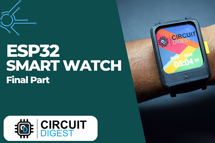
Experience the thrill of creating your own ESP32 DIY smartwatch with multiple watch faces, heart rate sensor, compass, and games! Our step-by-step guide will help you build a one-of-a-kind wearable device that's as unique as you are. Start your adventure today and make your own mark on the world of DIY smartwatches!
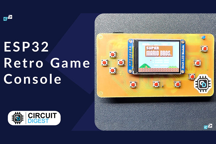
Take a trip down memory lane with our DIY handheld retro gaming console! Powered by the versatile ESP32, this console lets you relive classic games on-the-go with style and ease. Ready to build your own? Let's get gaming!
Take control of your energy usage with our DIY Power Consumption Monitoring Device! With ESP32 technology, easily track and analyze your energy consumption in real-time, helping you save money and reduce your carbon footprint!
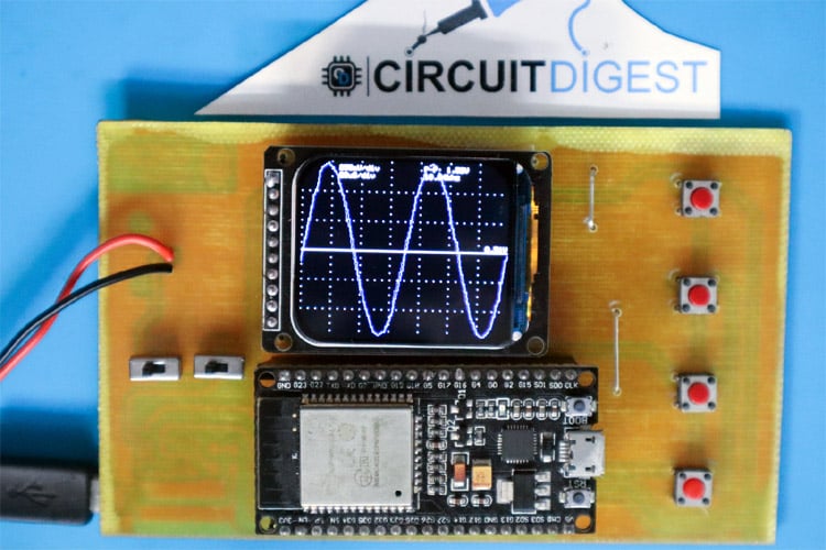
See the invisible with our DIY ESP32 Oscilloscope! Turn your ESP32 into a powerful tool for measuring and analyzing electronic signals. With easy-to-follow instructions, build your own oscilloscope and explore the world of electronics like never before. Perfect for hobbyists and professionals alike!
Complete Project Code
    // Load Wi-Fi library

    #include <WiFi.h>


    // Replace with your network credentials

    const char* ssid = "REPLACE_WITH_YOUR_SSID";

    const char* password = "REPLACE_WITH_YOUR_PASSWORD";


    // Set web server port number to 80

    WiFiServer server(80);


    // Variable to store the HTTP request

    String header;


    // Auxiliary variables to store the current output state

    String output12State = "off";

    String output14State = "off";


    // Assign output variables to GPIO pins

    const int output12 = 12;

    const int output14 = 14;


    // Current time

    unsigned long currentTime = millis();


    // Previous time

    unsigned long previousTime = 0;


    // Define timeout time in milliseconds (example: 2000ms = 2s)

    const long timeoutTime = 2000;


    void setup() {

      Serial.begin(115200);


      // Initialize the output variables as outputs

      pinMode(output12, OUTPUT);

      pinMode(output14, OUTPUT);


      // Set outputs to LOW

      digitalWrite(output12, LOW);

      digitalWrite(output14, LOW);


      // Connect to Wi-Fi network with SSID and password

      Serial.print("Connecting to ");

      Serial.println(ssid);

      WiFi.begin(ssid, password);


      while (WiFi.status() != WL_CONNECTED) {

        delay(500);

        Serial.print(".");

      }


      // Print local IP address and start web server

      Serial.println("");

      Serial.println("WiFi connected.");

      Serial.println("IP address: ");

      Serial.println(WiFi.localIP());

      server.begin();

    }


    void loop() {

      WiFiClient client = server.available();   // Listen for incoming clients


      if (client) {                             // If a new client connects,

        currentTime = millis();

        previousTime = currentTime;

        Serial.println("New Client.");          // print a message out in the serial port

        String currentLine = "";                // make a String to hold incoming data from the client


        while (client.connected() && currentTime - previousTime <= timeoutTime) {  // loop while the client's connected

          currentTime = millis();


          if (client.available()) {             // if there's bytes to read from the client,

            char c = client.read();             // read a byte, then

            Serial.write(c);                    // print it out the serial monitor

            header += c;


            if (c == '\n') {                    // if the byte is a newline character

              // if the current line is blank, you got two newline characters in a row.

              // that's the end of the client HTTP request, so send a response:

              if (currentLine.length() == 0) {

                // HTTP headers always start with a response code (e.g. HTTP/1.1 200 OK)

                // and a content-type so the client knows what's coming, then a blank line:

                client.println("HTTP/1.1 200 OK");

                client.println("Content-type:text/html");

                client.println("Connection: close");

                client.println();


                // turns the GPIOs on and off

                if (header.indexOf("GET /12/on") >= 0) {

                  Serial.println("GPIO 12 on");

                  output12State = "on";

                  digitalWrite(output12, HIGH);

                } else if (header.indexOf("GET /12/off") >= 0) {

                  Serial.println("GPIO 12 off");

                  output12State = "off";

                  digitalWrite(output12, LOW);

                } else if (header.indexOf("GET /14/on") >= 0) {

                  Serial.println("GPIO 14 on");

                  output14State = "on";

                  digitalWrite(output14, HIGH);

                } else if (header.indexOf("GET /14/off") >= 0) {

                  Serial.println("GPIO 14 off");

                  output14State = "off";

                  digitalWrite(output14, LOW);

                }


                // Display the HTML web page

                client.println("<!DOCTYPE html><html>");

                client.println("<head><meta name=\"viewport\" content=\"width=device-width, initial-scale=1\">");

                client.println("<link rel=\"icon\" href=\"data:,\">");


                // CSS to style the on/off buttons

                // Feel free to change the background-color and font-size attributes to fit your preferences

                client.println("<style>html { font-family: Helvetica; display: inline-block; margin: 0px auto; text-align: center;}");

                client.println(".button { background-color: #4CAF50; border: none; color: white; padding: 16px 40px;");

                client.println("text-decoration: none; font-size: 30px; margin: 2px; cursor: pointer;}");

                client.println(".button2 {background-color: #555555;}</style></head>");


                // Web Page Heading

                client.println("<body><h1>ESP32 Web Server</h1>");


                // Display current state, and ON/OFF buttons for GPIO 12

                client.println("<p>GPIO 12 - State " + output12State + "</p>");

                // If the output12State is off, it displays the ON button

                if (output12State == "off") {

                  client.println("<p><a href=\"/12/on\"><button class=\"button\">ON</button></a></p>");

                } else {

                  client.println("<p><a href=\"/12/off\"><button class=\"button button2\">OFF</button></a></p>");

                }


                // Display current state, and ON/OFF buttons for GPIO 14

                client.println("<p>GPIO 14 - State " + output14State + "</p>");

                // If the output14State is off, it displays the ON button

                if (output14State == "off") {

                  client.println("<p><a href=\"/14/on\"><button class=\"button\">ON</button></a></p>");

                } else {

                  client.println("<p><a href=\"/14/off\"><button class=\"button button2\">OFF</button></a></p>");

                }


                client.println("</body></html>

