A stepper motor is a type of DC motor that works in discrete steps and used everywhere from a surveillance camera to sophisticated robots and machines. NEMA 17 stepper motor has a step angle of 1.8° that means it will take 200 steps for a 360° rotation. By changing the rate of the control signal applied, we can easily control the motor speed. Stepper motor can be operated in different step modes such as full step, half step, ¼ step by applying appropriate logic levels to microstep pins of stepper module. In our previous project, we controlled 28-BYJ48 stepper motor using Arduino. 28-BYJ48 has relatively lower torque than the other stepper motors like NEMA 14, NEMA17.
In this tutorial, we are going to control NEMA 17 stepper motor using Arduino and DRV8825 stepper module. We will also use a potentiometer to control the direction of the stepper motor to rotate it in clockwise and anti-clockwise direction. We previously controlled the same Nema17 stepper motor with A4988 stepper driver and Arduino.
Components Required
- Arduino UNO
- NEMA17 Stepper Motor
- DRV8825 Stepper Driver Module
- 47 µf Capacitor
- Potentiometer
Nema 17 Stepper Motor Driver- DRV8825
A stepper driver module controls the working of a stepper motor. Stepper drivers send the current to stepper motor through various phases.
The DRV8825 is a microstepping driver module similar to the A4988 module. It is used to control bipolar stepper motors. This Nema 17 stepper driver module has a built-in translator that means that it can control both speed and direction of a bipolar stepper motor like NEMA 17 using only two pins, i.e. STEP and DIR. STEP pin is used to control the steps, and DIR pin is used to control the direction of rotation.
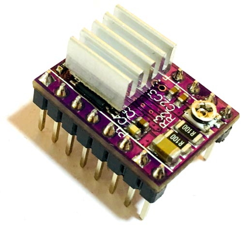
Nema 17 motor driver DRV8825 has a maximum output capacity of 45V and ± 2.2 A. This driver can operate stepper motor in six different step modes i.e. full-step, half-step, quarter-step, eighth-step, sixteenth-step, and thirty-second-step. You can change the step resolution using the microstep pins (M0, M1 & M2). By setting appropriate logic levels to these pins, we can set the motors to one of the six-step resolutions. The truth table for these pins is given below:
| M0 | M1 | M2 | Microstep Resolution |
| Low | Low | Low | Full Step |
| High | Low | Low | ½ Step (Half Step) |
| Low | High | Low | ¼ Step (Quarter Step) |
| High | High | Low | 1/8 Step (Eighth Step) |
| Low | Low | High | 1/16 Step (Sixteenth Step) |
| High | Low | High | 1/32 step (Thirty-second Step) |
| Low | High | High | 1/32 step (Thirty-second Step) |
| High | High | High | 1/32 step (Thirty-second Step) |
DRV8825 Stepper Motor Driver Module Specification
- Max. Operating Voltage: 45 V
- Min. Operating Voltage: 8.2 V
- Max. Current Per Phase: 2.5 A
- PCB Size: 15 mm x 20 mm
Features
- Six step resolution: Full step, ½ step, ¼ step, 1/8, 1/16 and 1/32 step
- Adjustable output current via potentiometer
- Automatic current decay mode detection
- Over-temperature shutdown circuit
- Under-voltage lockout
- Over-current shutdown
Difference between DRV8825 and A4988 Nema 17 Motor Drivers
A4988 and DRV8825 both have similar pinout and applications, but these modules have some differences in no. of micro steps, operating voltage, etc. Some key differences are given below:
- The DRV8825 offers six-step modes, whereas the A4988 offers five-step modes. Higher step modes result in smoother, quieter operation.
- Minimum STEP pulse duration for DRV8825 is 1.9µs, while for A4988 STEP pulse duration is 1µs.
- The DRV8825 can deliver slightly more current than the A4988 without any additional cooling.
- Location of the current limit potentiometer is different in both modules.
- The DRV8825 can be used with a higher voltage motor power supply.
- The SLEEP pin on the DRV8825 is not pulled up by default like it is on the A4988.
- Instead of the supply voltage pin, DRV8825 has FAULT output pin.
Circuit Diagram
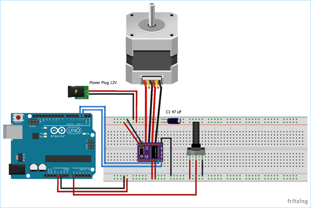
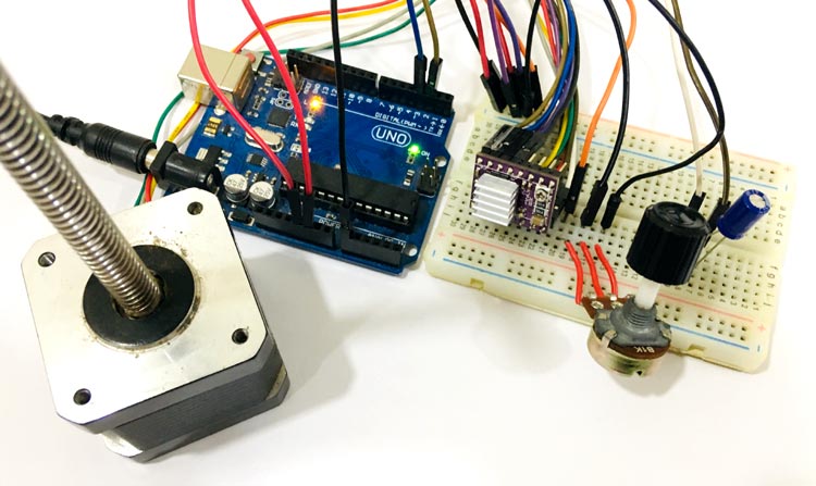
Circuit diagram to control Nema 17 with Arduino is given in the above image. Stepper motor is powered using a 12V power source, and the DRV8825 module is powered via Arduino. RST and SLEEP pin both connected to the 5V on the Arduino to keep the driver enabled. Potentiometer is connected to A0 pin of Arduino; it is used to control the direction of the motor. If you turn the potentiometer clockwise, then stepper will rotate clockwise, and if you turn potentiometer anticlockwise, then it will rotate anticlockwise. A 47 µf capacitor is used to protect the board from voltage spikes. M0, M1, and M2 pins left disconnected, that means the driver will operate in full-step mode.
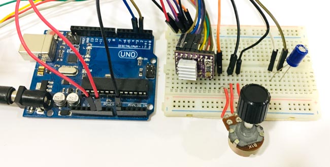
Complete connections for Arduino Nema 17 DRV8825 are given in below table.
|
S.NO. |
DRV8825 Pin |
Connection |
|
1 |
VMOT |
+ve Of Battery |
|
2 |
GND |
-ve of Battery |
|
3 |
RST |
5V of Arduino |
|
4 |
SLP |
5V of Arduino |
|
5 |
GND |
GND of Arduino |
|
6 |
STP |
Pin 3 of Arduino |
|
7 |
DIR |
Pin 2 of Arduino |
|
8 |
B2, B1, A1, A2, |
Stepper Motor |
Current limiting
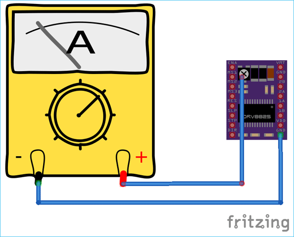
Before using the motor, change the current limit of DRV8825 module to 350mA using the current limiting potentiometer. You can measure the current limit using multimeter. Measure the current between two points GND and the potentiometer and adjust it to the required value.
Code Explanation
Complete code with a working video to control Nema 17 with Arduino is given at the end of this tutorial, here we are explaining the complete program to understand the working of the project.
First of all, add the stepper motor library to your Arduino IDE. You can download the stepper motor library from here.
After that define the no of steps for the NEMA 17. The no. of steps per revolution for NEMA 17 is 200.
#include <Stepper.h>
#define STEPS 200
After that, specify the pins to which driver module is connected and define the motor interface type as Type1 because the motor is connected through the driver module.
Stepper stepper(STEPS, 2, 3);
#define motorInterfaceType 1
Next set the speed for stepper motor using stepper.setSpeed function. Maximum motor speed for NEMA 17 is 4688 RPM but if we run it faster than 1000 RPM torque falls of quickly.
void setup() {
    stepper.setSpeed(800);
Now in the main loop, we will read the potentiometer value from A0 pin. In this loop, we are using two functions one is potVal, and the other is Pval. If the current value, i.e., potVal is higher than the previous value, than it will move ten steps in the clockwise direction and if the current value is less than previous value than it will move ten steps in the counter-clockwise direction.
potVal = map(analogRead(A0),0,1024,0,500);
  if (potVal>Pval)
      stepper.step(10);
  if (potVal<Pval)
      stepper.step(-10);
Pval = potVal;
Now connect the Arduino with your laptop and upload the code into your Arduino UNO board using Arduino IDE, select the Board and port no and then click on the upload button.
Now you can control the direction of the Nema17 stepper motor using the potentiometer. The complete working of the Nema 17 with Arduino is shown in the video below. If you have any doubts regarding this project, post them in the comment section below.
Complete Project Code
#include <Stepper.h>

#define STEPS 200

//#define dirPin 2

//#define stepPin 3

// Define stepper motor connections and motor interface type. Motor interface type must be set to 1 when using a driver:

Stepper stepper(STEPS, 2, 3);

#define motorInterfaceType 1

int Pval = 0;

int potVal = 0;
void setup() {

  // Set the maximum speed in steps per second:

  stepper.setSpeed(800);

 // pinMode(stepPin, OUTPUT);

 // pinMode(dirPin, OUTPUT);

}

void loop() {


  potVal = map(analogRead(A0),0,1024,0,500);

  if (potVal>Pval)

      stepper.step(10);

  if (potVal<Pval)

      stepper.step(-10);
Pval = potVal;


}

