A few years ago, building a drone was expensive and out of reach for most hobbyists and students. But today, DIY drones have become more accessible and affordable. With the LiteWing Drone—a compact, open-source drone powered by the ESP32—you can build and fly your own drone for under $50. It's beginner-friendly, ready to fly out of the box, and can be controlled via a mobile app, Python code, or even custom firmware using the Arduino IDE.
Table of Contents
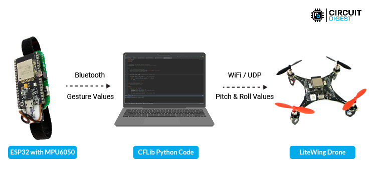
In this article, we are going to show you how you can build a gesture control drone. To do this we will obviously need a drone which in our case is a LiteWing Drone and to control this drone we will use an ESP32 dev module along with a mpu6050 both of which are strapped to our hand. Basically, we will read the gestures from the hand using MPU6050 and send it to our computer via Bluetooth. Then on the computer we will write a small python code to read these Bluetooth values and use them to control the X (pitch) and Y(roll) direction of the drone through UDP communication. Now all this might sound complicated, but I am going to show you step by step on how to build this easily, so let’s get started
Pre-requisites
Before we get started, it is important for you to understand the basics of drone and how to fly it. If you are completely new to LiteWing Drones, I would suggest you to start with how to fly LiteWing Drones before you continue with this project. You can also read about how to control your drone using python code.
Components Required
1. LiteWing Drone with battery
2. VLX5311x ToF Sensor For height hold
3. ESP32 dev module and mpu6050 for gesture control
4. A computer with python installed
Build a Wrist band with ESP32 and MPU6050 for Reading Hand Gestures
Let’s start by building our hand gesture controller first. We have built a lot of gesture control projects, previously here on CircuitDigest and there are many way to get it done. While using OpenCV for hand gesture looks more cool and does not need any hardware, it is not very reliable and fast enough to control a drone which is why we will be using an MPU6050 and ESP32 to build our little hand gesture recognition device like shown below.
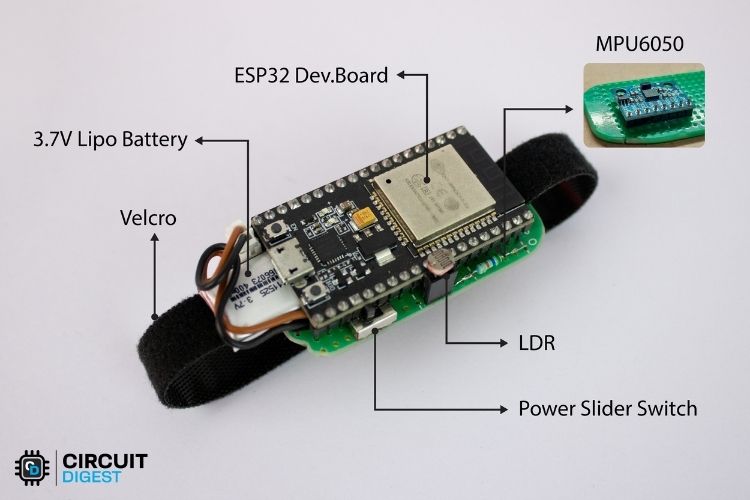
As you can see, we only have an ESP32 connected to an LDR sensor and the MPU6050 (placed under the ESP32 board). Using this MPU6050 we will sense how much our hand is tilted to the left and right (X-axis) and front and back (Y-axis). We will then pass these X and Y values to our drone to control the Roll and Pitch of the drone respectively. The LDR sensor is used as a trigger switch, when we close our fist the LDR sensor will detect darkness and arm the drone for take-off, once we open the wrist it will stop the throttle and the drone will stop flying.
The whole set up is powered by a 3.7V Li-Po battery and we also have a switch to turn on and off the device and a hook up strap to mount this to our hand. The complete circuit diagram for the hand gesture device is shown below.

You can either build this circuit on a zero PCB like shown here or you can also simply build it on a breadboard. You can also follow our ESP32 Air mouse project to get more details on how to build a gesture control device. Once your hardware is ready to you can upload the Arduino code from below
/*
Features:
- Reads acceleration and gyroscope data from an MPU6050 sensor.
- Uses a Kalman filter to smooth and correct sensor readings.
- Reads ambient light levels using an LDR sensor.
- Communicates sensor data wirelessly via Bluetooth.
- Sends processed values over serial for debugging.
Applications:
- Motion tracking and gesture recognition.
- Balancing robots and stabilization systems.
- Smart lighting systems based on ambient light levels.
- Wearable motion analysis and health tracking.
- Wireless remote control based on tilt movements.
*/
#include <Adafruit_MPU6050.h>
#include <Adafruit_Sensor.h>
#include <Wire.h>
#include "BluetoothSerial.h"
Adafruit_MPU6050 mpu;  // Create MPU6050 sensor object
BluetoothSerial SerialBT;  // Create Bluetooth serial object
const int LDRSensor = 34;  // Define the LDR sensor pin
// Kalman filter variables
float x_angle = 0, y_angle = 0; // Filtered angle estimates
float x_bias = 0, y_bias = 0;   // Gyroscope bias correction
float P[2][2] = { { 1, 0 }, { 0, 1 } };  // Error covariance matrix
// Kalman filter tuning parameters
// Adjust these for different levels of noise filtering and responsiveness
// Quick and Less Smooth Response
float q_angle = 0.01;    // Trust new angle estimates more
float q_bias = 0.01;     // Faster correction of gyroscope drift
float r_measure = 0.01;  // Trust sensor readings more (less smoothing)
// // Alternative: Optimum Response
// const float q_angle = 0.001; // Process noise
// const float q_bias = 0.003;
// const float r_measure = 0.03; // Measurement noise
// // Alternative: Slow and smooth response
// float q_angle = 0.0001;   // Trust new angle estimates more
// float q_bias = 0.0005;    // Faster correction of gyroscope drift
// float r_measure = 0.05;   // Trust sensor readings more (less smoothing)
void setup() {
Serial.begin(115200);  // Initialize Serial Monitor
SerialBT.begin("ESP32_BT");  // Initialize Bluetooth with device name "ESP32_BT"
// Initialize MPU6050 sensor
if (!mpu.begin()) {
  Serial.println("MPU6050 not found!");
  while (1) delay(10);  // Halt execution if MPU6050 is not detected
}
// Set MPU6050 configuration
mpu.setAccelerometerRange(MPU6050_RANGE_8_G);  // Set accelerometer range
mpu.setGyroRange(MPU6050_RANGE_500_DEG);       // Set gyroscope range
mpu.setFilterBandwidth(MPU6050_BAND_10_HZ);    // Apply a low-pass filter
delay(100);  // Allow settings to take effect
}
// Kalman filter function to smooth sensor data
float kalmanFilter(float newAngle, float newRate, float dt, float &angle, float &bias) {
float rate = newRate - bias;  // Remove bias from gyroscope rate
angle += dt * rate;  // Estimate new angle
// Update estimation error covariance
P[0][0] += dt * (dt * P[1][1] - P[0][1] - P[1][0] + q_angle);
P[0][1] -= dt * P[1][1];
P[1][0] -= dt * P[1][1];
P[1][1] += q_bias * dt;
// Compute Kalman gain
float S = P[0][0] + r_measure;
float K[2] = { P[0][0] / S, P[1][0] / S };
// Update estimates with measurement
float y = newAngle - angle;
angle += K[0] * y;
bias += K[1] * y;
// Update error covariance matrix
P[0][0] -= K[0] * P[0][0];
P[0][1] -= K[0] * P[0][1];
P[1][0] -= K[1] * P[0][0];
P[1][1] -= K[1] * P[0][1];
return angle;  // Return the filtered angle
}
void loop() {
sensors_event_t a, g, temp;  // Variables to store sensor readings
mpu.getEvent(&a, &g, &temp); // Get sensor data
int ldrValue = analogRead(LDRSensor);  // Read LDR sensor value
int outputValue = (ldrValue < 2000) ? 0 : 1;  // Determine light or dark condition
// Calculate time difference for Kalman filter
static unsigned long prevTime = millis();
float dt = (millis() - prevTime) / 1000.0;  // Convert to seconds
prevTime = millis();
// Apply Kalman filter to smooth sensor data
float filteredX = kalmanFilter(a.acceleration.x, g.gyro.x, dt, x_angle, x_bias);
float filteredY = kalmanFilter(a.acceleration.y, g.gyro.y, dt, y_angle, y_bias);
// Format data for Bluetooth transmission
String btData = String(filteredX, 2) + "," + String(filteredY, 2) + "," + String(outputValue);
// Send data over Bluetooth and Serial for debugging
SerialBT.println(btData);
Serial.println(btData);
// Small delay to stabilize loop execution
// delay(1); // Uncomment if needed
}
The code is pretty simple, we are going to read the X and Y values from the accelerometer and gyroscope and then use something called Kalman Filter to get more accurate motion tracking. The reading from accelerometer is noisy but stable in the long term, while the reading from gyroscope drifts over time. So Kalman filter combines both to minimize the noise and drift. This results in a smooth reliable readings on orientation as we will see later. Kalman filter is a very interesting topic and is very commonly used in drones and self-balancing robots you can check then out if interested.
Along with the filtered X and Y values we will also read the value from LDR using analog read and output all these three values in format “X, Y, throttle” in both the serial monitor as well as via Bluetooth serial. You can also notice in the code that we have named our Bluetooth signal as “ESP32-BT”.
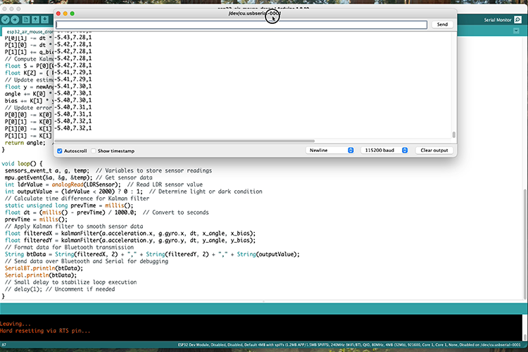
After uploading the code, you can open the serial monitor and check the values of X,Y, and throttle as shown in the above image. The values of X and Y should be close to zero when you hand is flat to the ground and as you tilt to the left it will vary from 0 to -10 and when you tilt to right it will vary from 0 to +10. The same should also happen when you move your hand from top to bottom. This X and Y values will later translate to the roll and pitch for the drone.
Height Hold on LiteWing
Before we start controlling the drone with gestures, it is recommended to implement height hold on our LiteWing drone. This way when the drone starts flying it will maintain a set height on its own. Now, you can choose to control the height also with gestures but when we tried it, we found too hard to control the drone which is why we are implemented height hold and decided to control only the yaw and pitch of the drone through gestures.
Implementing height hold on our LiteWing esp32 drone is very easy. All you need is the VL53L1 ToF sensor and you can directly solder in on the designed pads found on the bottom of the drone. Our drone with the ToF sensor soldered can be found below
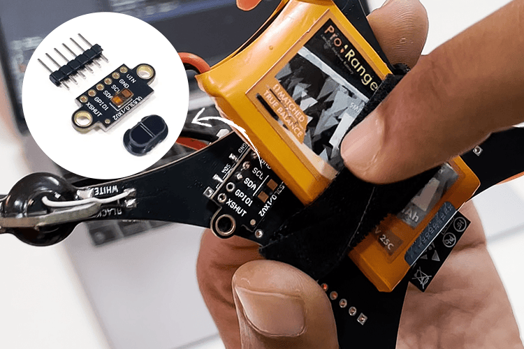
The default firmware that gets shipped with LiteWing supports crazyflie cfclient and cflib. When the drone boots up if it finds the sensor connect to it, it will automatically start reading values form the sensor when height hold is enabled. And height hold can be enabled either via cfclient or inside the python code using cflib. Will discuss more about this later in this article.
Python Code for Drone Gesture Control
Now that you have your gesture control hardware ready for tracking and the LiteWing drone with the VL53L1 sensor soldered. Let’s start writing a python code to read the values of X, Y and throttle form the gesture control hardware via Bluetooth and send these values to our drone to control the pitch and roll. Before we do that it’s important for you to check if you LiteWing drone is working properly, follow this getting started with LiteWing tutorial to fly your drone with ESP-Drone mobile application this will help us ensure that the drone is working well and is ready to fly using commands from python. The complete python code used in this project can be found at the bottom of this page, the code explanation is as follows.
Do note that the cflib python package has to be installed separately from our github repo, we are using pycharm and if you are too then Open a new project on PyCharm and get into the terminal to follow the below steps and install cflib
Step 1: Use the code below to clone into the repository.
git clone https://github.com/jobitjoseph/crazyflie-clients-python.git
cd crazyflie-clients-python
Step 2: Install dependencies, cfclient and cflib using the below line
pip3 install -e .We start our code by calling the required python libraries. LiteWing drones also have URI address to identify the drone in network, the address will always be 192.168.43.42 we will communicating using UDP protocol to our drone using this address. Note that you have to be connect to the drone via wifi for this UDP connection to work
import time
import cflib.crtp
from cflib.crazyflie import Crazyflie
import serial
# URI for your LiteWing drone
DRONE_URI = "udp://192.168.43.42"
Next, we initialize a serial monitor to communicate with our gesture control device wirelessly using Bluetooth. Now when a Bluetooth device is connected to your laptop it opens a port through which we can communicate wirelessly. I am using a mac and we have named our Bluetooth device as “ESP32_BT” so the code looks like this. Make sure to change the port address based on the computer you are using. Alternatively, if you do not want to use Bluetooth you can also connect the gesture control esp32 board directly to laptop and use serial communication.
# Connect to serial port
#ser = serial.Serial('/dev/cu.usbserial-0001', 115200, timeout=1) #use for serial wire connection
ser = serial.Serial("/dev/tty.ESP32_BT", baudrate=9600, timeout=1) #use for bluetooth connection
print("Connected to BT")
We will initialize the CRTP (Crazy Real Time Protocol) drivers to communicate with out drone is real time via UDP. We will open a link using the DRONE_URI address and then arm the done using commander.send_setpoint. Also activate high level commander using “commander.enHighLevel”. Now these two lines might sound completely new but you can check out this cflib documentation to learn more. Do note that LiteWing supports only the basic commands from cflib.
# Initialize CRTP drivers
cflib.crtp.init_drivers()
# Create Crazyflie instance
cf = Crazyflie()
# Connect to the drone
print("Connecting to drone...")
cf.open_link(DRONE_URI)
print("Connected to drone. Waiting for stability...")
time.sleep(1.0)  # Wait after connection
# First send zero setpoint to unlock safety
print("Sending zero setpoint to unlock safety...")
cf.commander.send_setpoint(0, 0, 0, 0)
time.sleep(0.1)
cf.param.set_value('commander.enHighLevel', '1')
print("High-level commander activated")
Now inside an infinite while loop, we will read the values from our gesture control device and we split the values using “,” as separator. We send map down these values of 0 to 10 to 0 to 1 and send it as vx and vy to the drone. As the values get changes the pitch and roll of the drone will be controlled in real time.
while True:
   try:
       # Read a line of data
       line = ser.readline().decode('utf-8').strip()
       # Check if there's data
       if line:
           # Split the data and extract values
           values = line.split(',')
           # Clean the values before converting to float
           # This removes any duplicate decimal points
           clean_x = values[0].replace('0.0', '0.', 1) if '0.0' in values[0] else values[0]
           clean_y = values[1].replace('0.0', '0.', 1) if '0.0' in values[1] else values[1]
           trigger = values[2]
           if trigger == "0":
               cf.commander.send_setpoint(0, 0, 0, 0)
               ser.reset_input_buffer()
               print("waiting for trigger")
           if trigger == "1":
               gyroX = float(clean_x)
               gyroY = float(clean_y)
               # Map gyroX and gyroY (-5 to +5) to vx and vy (-0.5 to +0.5)
               vx = round(gyroX / 10.0, 1)  # Rounded to 1 decimal place
               vy = -round(gyroY / 10.0, 1)  # Rounded to 1 decimal place
               # Print only gyroX and gyroY
               print(vx, vy, trigger)
               cf.commander.send_hover_setpoint(vx, vy, 0, 0.5)
   except:
       # Skip any problematic lines
       pass
Testing our Gesture Controlled Drone
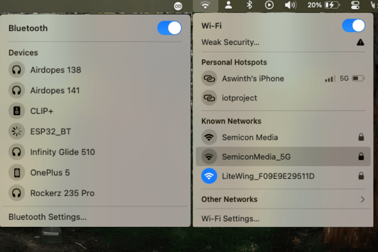
Now that everything is ready all that is left is to start flying our drone and have fun. Simple power on the drone and the gesture-controlled device. Make sure you are connected to the gesture-controlled device using Bluetooth and the drone using Wi-Fi as you can see in the below images.
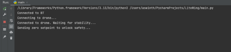
Then start your python script and you should be able to see the python code trying to connect with our drone, each time the LiteWing drone receives data package from our code it will blink the on-board blue LED called which is marked as “Link”. When everything is ready you can see the console saying “Waiting for trigger” now you can close your fist to trigger the drone and start flying it.
You can check out the video below to see the drone in action. It might take some time for you to get used to controlling the drone. If you need more stability, you can also implement position hold using optical flow sensor or UWB. We plan to cover more tutorials on this later and you can check them out on our LiteWing Documentation page.
Projects using Gesture Control
Explore practical gesture control projects from Circuit Digest, including air mouse, LED control, and Bluetooth keyboard, ideal for learning and simple DIY applications.

Hand Gesture Recognition using ESP32 and Python
Learn how to control LEDs using hand gestures with an ESP32 and Python. This simple project uses MPU6050 sensor data to detect motion and trigger LED actions via Bluetooth.

Gesture based Intelligent Appliance Control Robot
Build a simple robot that responds to hand gestures using Arduino, MPU6050, and nRF24L01 for wireless control.

Control your Computer with Hand Gestures using Arduino
Create a budget-friendly gesture control system for your laptop or computer using Arduino and Python. Utilize ultrasonic sensors to track hand movement and control media players or other applications effortlessly.

Hand Gesture Controlled Robotic Arm using Arduino Nano
Learn how to create a hand gesture-controlled robotic arm using Arduino Nano, an MPU6050 Gyroscope, and a flex sensor. This project enables you to manipulate a 3D printed robotic arm's movement and gripper, mimicking human hand gestures for precise control.

Gesture based Intelligent Appliance Control Robot
Explore how AI-powered hand gesture recognition can be used to control home appliances, from adjusting lighting and fan speed to operating door stoppers. Inspired by Iron Man's Jarvis, this project makes smart home automation more accessible, especially for those with limited mobility.
Complete Project Code
import time
import cflib.crtp
from cflib.crazyflie import Crazyflie
import serial
# URI for your LiteWing drone
DRONE_URI = "udp://192.168.43.42"
# Connect to serial port
#ser = serial.Serial('/dev/cu.usbserial-0001', 115200, timeout=1) #use for serial wire connection
ser = serial.Serial("/dev/tty.ESP32_BT", baudrate=9600, timeout=1) #use for bluetooth connection
print("Connected to BT")
# Give the serial connection time to establish
time.sleep(1)
# Initialize CRTP drivers
cflib.crtp.init_drivers()
# Create Crazyflie instance
cf = Crazyflie()
# Connect to the drone
print("Connecting to drone...")
cf.open_link(DRONE_URI)
print("Connected to drone. Waiting for stability...")
time.sleep(1.0)  # Wait after connection
# First send zero setpoint to unlock safety
print("Sending zero setpoint to unlock safety...")
cf.commander.send_setpoint(0, 0, 0, 0)
time.sleep(0.1)
cf.param.set_value('commander.enHighLevel', '1')
print("High-level commander activated")

# Clear any initial data from serial
ser.reset_input_buffer()
# Read data continuously
while True:
   try:
       # Read a line of data
       line = ser.readline().decode('utf-8').strip()
       # Check if there's data
       if line:
           # Split the data and extract values
           values = line.split(',')
           # Clean the values before converting to float
           # This removes any duplicate decimal points
           clean_x = values[0].replace('0.0', '0.', 1) if '0.0' in values[0] else values[0]
           clean_y = values[1].replace('0.0', '0.', 1) if '0.0' in values[1] else values[1]
           trigger = values[2]
           if trigger == "0":
               cf.commander.send_setpoint(0, 0, 0, 0)
               ser.reset_input_buffer()
               print("waiting for trigger")
           if trigger == "1":
               gyroX = float(clean_x)
               gyroY = float(clean_y)
               # Map gyroX and gyroY (-5 to +5) to vx and vy (-0.5 to +0.5)
               vx = round(gyroX / 10.0, 1)  # Rounded to 1 decimal place
               vy = -round(gyroY / 10.0, 1)  # Rounded to 1 decimal place
               # Print only gyroX and gyroY
               print(vx, vy, trigger)
               cf.commander.send_hover_setpoint(vx, vy, 0, 0.5)
   except:
       # Skip any problematic lines
       pass