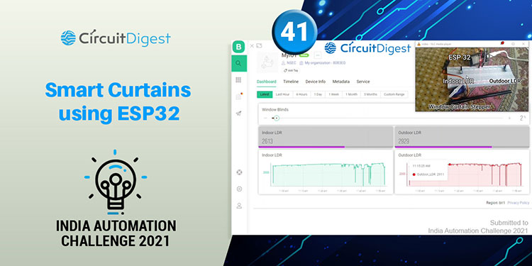
You’d be surprised at how much curtains matter in the house! Aside from keeping the peeping Toms out (especially in a crowded place like India, where flats are stacked window to window), they play an important role in decor by creating ambiance and pulling the room together kind of like rugs. When comes to decor, curtains play an important role in automation. Very few have thought of this area. When thinking of home automation no one thinks of these, but this will add some extra stars to show off. My attempt is to create a prototype version of Smart Curtains using ESP32. I’ve used basic sensors and actuators, but you can scale it up if you want. With my approach you can control your room lighting to your need, setting customized light intensity as your mood, or even while you’re away. I’ve used servos to represent stepper motor which would be used to draw the curtains or window panels. I’ve used two LDR(light-dependent resistors) to take feedback of outdoor and indoor lighting conditions and set servo in such a level to let that much amount of light enter the room. I’ve used ESP32 as the main microcontroller, it connects to the network and listens for any change of servo position, and reports indoor and outdoor lighting to the network. I’ve used the Blynk IOT platform here, it acts as a middle man between the user phone and actual hardware. It sends data to the phone and takes input from the user. Different people have their own preferences, some prefer more light, while some prefer darkness.
Component Required for Smart Curtains

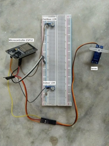
Project Used Hardware
- ESP32 x1,
- LDR x2,
- 10kOhm Resistor x2,
- Servo x1,
- Some Jumpers,
- Power Adapter,
- Breadboard,
- Common hardware tools
Project Used Software
- Arduino,
- Blynk IoT Platform
Project Hardware Software Selection
ESP32 is just the right hardware to go for. Considering its price, it offers some serious advantages over any other IoT board in the market. For demo purposes, I've used Servo in place of Stepper Motor. Two LDR are used as feedback for the system to act accordingly. Users can control the percentage of light entering from any part of the world at a comfort. Different users have different preferences, so gives customization. Programming ESP32 using the Arduino platform is a breeze, it's open-source and already has a wide user base. At any point in time if you're stuck you can just search it online. For DIY projects, open-source is the way to go.
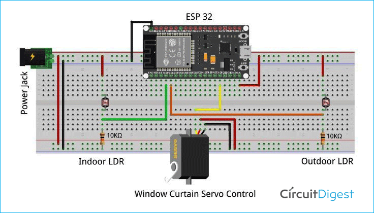
Smart Curtains Circuit Diagram
The circuit is very simple. Any kid will also be able to make it. You just need basic breadboard skills. Connect wires as per circuit shown. I've connected the servo to pin 13. Indoor LDR to pin 34, since it's an analog pin. Outdoor LDR to pin 35 since it's also an analog pin. Just these basic wiring will get up and running. Very easy. Make a voltage divider using LDR and 10kOhm resistor. This voltage divider will give different output voltages for different lighting exposed. Make the voltage divider by referring to the circuit. Connect all ground wires together and connect it to the power supply. Same for power line also.
Complete Project Code
// Template ID, Device Name and Auth Token are provided by the Blynk.Cloud
// See the Device Info tab, or Template settings
#define BLYNK_TEMPLATE_ID           "xxxxxxxxxxxxxxxxx" //Paste your template ID here
#define BLYNK_DEVICE_NAME           "MyIOT" //Paste your device name
#define BLYNK_AUTH_TOKEN            "xxxxxxxxxxxxxxxxx" //Paste your Auth Token

#define blinds 13
#define indoor 34
#define outdoor 35
// Comment this out to disable prints and save space
//#define BLYNK_PRINT Serial
//#include <WiFi.h>
//#include <WiFiClient.h>
#include <BlynkSimpleEsp32.h>

#include <ESP32Servo.h>
Servo myservo;

char auth[] = BLYNK_AUTH_TOKEN;

// Your WiFi credentials.
// Set password to "" for open networks.
char ssid[] = "xxxxxxxxx"; //Enter your credentials
char pass[] = "xxxxxxxxx";

BlynkTimer timer;

// This function is called every time the Virtual Pin 0 state changes
BLYNK_WRITE(V0)
{
  // Set incoming value from pin V0 to a variable
  int value = param.asInt();
  myservo.write(map(value, 0, 100, 0, 180));
}
// This function sends Arduino's uptime every second to Virtual Pin 2.
void myTimerEvent()
{
  // You can send any value at any time.
  // Please don't send more that 10 values per second.
  Blynk.virtualWrite(V1, analogRead(indoor));
  Blynk.virtualWrite(V2, analogRead(outdoor));
}

void setup()
{
  // Debug console
  Serial.begin(115200);
  ESP32PWM::allocateTimer(0);
  ESP32PWM::allocateTimer(1);
  ESP32PWM::allocateTimer(2);
  ESP32PWM::allocateTimer(3);
  myservo.setPeriodHertz(50);    // standard 50 hz servo
  myservo.attach(blinds, 1000, 2000);
  pinMode(indoor, INPUT);
  pinMode(outdoor, INPUT);

  Blynk.begin(auth, ssid, pass);
  // You can also specify server:
  //Blynk.begin(auth, ssid, pass, "blynk.cloud", 80);
  //Blynk.begin(auth, ssid, pass, IPAddress(192,168,1,100), 8080);

  // Setup a function to be called every second
  timer.setInterval(1000L, myTimerEvent);
}

void loop()
{
  Blynk.run();
  timer.run();
  // You can inject your own code or combine it with other sketches.
  // Check other examples on how to communicate with Blynk. Remember
  // to avoid delay() function!
}


