ESP32 is one of the most popular Wi-Fi based microcontroller modules and it is a popular choice in many Portable IoT Applications. It is a powerful controller that supports Dual Core Programming and also has in-built Bluetooth Low Energy (BLE) support making it a good choice for portable applications like in iBeacon devices, GPS Trackers, etc. However, in Battery-powered applications like these, the major concern is battery backup. This battery backup can be increased by smarter control over the microcontroller unit like one can program ESP32 in sleep mode during the ideal condition to increase the battery backup of the device.
In this project, we will check the current consumption of widely popular Wi-Fi and Bluetooth enabled microcontroller unit ESP32 in normal working mode and deep sleep mode. Also, we will test the difference and check how to put the ESP32 in deep sleep mode. You can also check out the article on how to minimize power consumption in microcontrollers for other tips that can be used to make your design much more power-efficient. Furthermore, if you are interested in the sleep mode of other microcontrollers you can chek out Arduino Sleep mode and ESP8266 NodeMCU Sleep mode as well.
Requirements
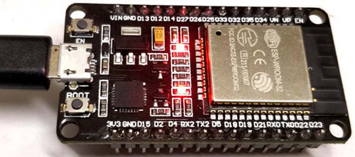
To do this, we will use ESP32 based Devkit V4.0 from Espressif that has USB to UART bridge as well as other ESP32 pinouts for easy connection. The programming will be done with Arduino IDE. If you are completely new, then for Getting started with ESP32 using Arduino, read the linked article before you proceed.
The requirements of this project are the following-
- It will go into the deep sleep mode by a press of a button.
- It will wake up from the deep sleep mode by the press of another button.
- To detect the state of the ESP32, a LED will blink with a turn-on time of 1000 milliseconds. During the sleep mode, it will be turned off.
Therefore, additional components required-
- LED - 1 pc
- Push-button (Tactile switch) - 2 pcs
- 4.7k resistors - 2 pcs
- 680R resistor - 1 pc
- Breadboard
- Hook up wire
- 5V adapter or power supply unit
- A micro-USB cable
- Arduino IDE with ESP32 programming interface in a PC or Laptop.
ESP32 Sleep Mode Circuit Diagram
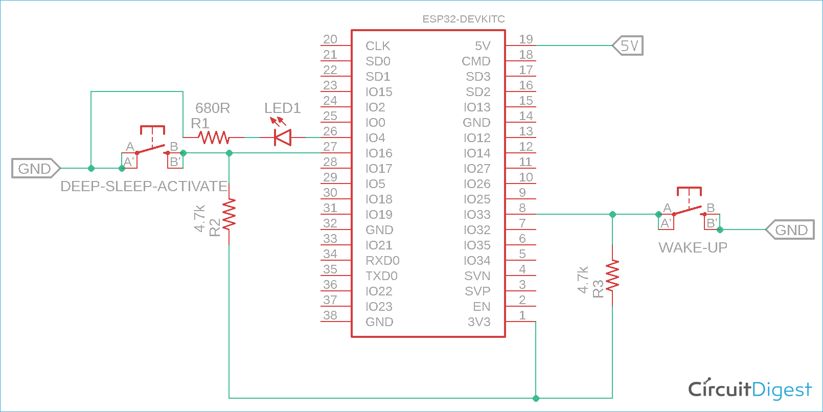
The schematic to put ESP32 to sleep on with push button is shown below.
The schematic is pretty simple. It has two buttons. The sleep button will put the ESP32 in deep sleep mode and another switch is used for waking up the ESP32 from sleep mode. Both buttons are connected in PIN 16 and PIN 33. Both buttons are configured as active low when pressed, therefore an additional pull-up is given. However, to detect whether the ESP 32 is in sleep mode or normal working condition mode, LED is connected to IO Pin 4.
Overview of Sleep Modes in ESP32
There are many different power modes for ESP32, namely active mode, modem sleep mode, light sleep mode, deep sleep mode, and hibernation mode.
During the normal working condition, the ESP32 runs on active mode. During ESP32 active mode, the CPU, WiFi/BT hardware, RTC memory, and RTC peripherals, ULP co-processors, all are activated and work depending on the workload. However, on different power modes, one or more peripherals are turned off. To check different power mode operations, follow the table below-
|
Hardware |
Active Mode |
Modem-sleep Mode |
Light Sleep Mode |
Deep-sleep Mode |
Hibernation |
|
CPU |
ON |
ON |
PAUSE |
OFF |
OFF |
|
WiFi/BT |
ON |
OFF |
OFF |
OFF |
OFF |
|
RTC and RTC Peripherals |
ON |
ON |
ON |
ON |
OFF |
|
ULP-Co Processor |
ON |
ON |
ON |
ON/OFF |
OFF |
As we can see in the above table that in ESP32 deep sleep mode that is often called as ULP sensor monitored pattern - the CPU, WiFi/BT, RTC memory and peripherals, ULP co-processors all are turned off. Only the RTC memory and RTC peripherals are turned on.
During the wake-up situation, the ESP32 needs to be notified by a wake-up source that will wake up the ESP32 from the deep sleep mode. However, since the RTC peripherals are turned on, the ESP32 can be wake up through RTC enabled GPIOs. There are other options as well. It can be wake up through an external wake up interrupt pins or using a timer to wake up the ESP32. In this project, we are using ext0 wakeup on pin 33.
Programming ESP32 for Deep Sleep Mode
The complete program can be found at the bottom of this page. It is written for Arduino IDE and can hence be easily adapted into your requirements. The explanation of the code is as follows.
At the beginning of the code,
//Create a PushButton variable
PushBnt pushBtn = {GPIO_NUM_16, 0, false};
// define Led Pin
uint8_t led_pin = GPIO_NUM_4;
// define wake up pin
uint8_t wakeUp_pin = GPIO_NUM_33;
The above three lines define the wake-up pin, LED pin, and the sleep mode pin.
void setup() {
  // put your setup code here, to run once:
  // set the serial port at 115200
  Serial.begin(115200);
  delay(1000);
  // set the pushButton pin as input with internal PullUp
  pinMode(pushBtn.pin, INPUT_PULLUP);
  // set the Interrupt handler with the pushButton pin in Falling mode
  attachInterrupt(pushBtn.pin, isr_handle, FALLING);
  // set the Led pin as ouput
  pinMode(led_pin, OUTPUT);
  //create a task that will be executed in the blinkLed() function, with priority 1 and executed on core 0
  xTaskCreate(
              blinkLed,   /* Task function. */
              "blinkLed",     /* name of task. */
              1024*2,       /* Stack size of task */
              NULL,        /* parameter of the task */
              5,           /* priority of the task */
              &taskBlinkled);      /* Task handle to keep track of created task */
  delay(500);
  //Configure Pin 33 as ext0 wake up source with LOW logic level
  esp_sleep_enable_ext0_wakeup((gpio_num_t)wakeUp_pin, 0);
}
In the above, the interrupt is set to a falling mode by the code snippet
attachInterrupt(pushBtn.pin, isr_handle, FALLING);
Therefore, whenever the switch is pressed, the logic level will get changed from logic 1 (3.3V) to logic 0 (0V). The voltage of the button pin will fall and the ESP32 will identify that the switch is pressed. There is also a task created to blink the LED.
 xTaskCreate(
              blinkLed,   /* Task function. */
              "blinkLed",     /* name of task. */
              1024*2,       /* Stack size of task */
              NULL,        /* parameter of the task */
              5,           /* priority of the task */
              &taskBlinkled);      /* Task handle to keep track of created task */
  delay(500);
The pin 33 is also configured using the below code snippet as an external wake up source identified as ext0.
esp_sleep_enable_ext0_wakeup((gpio_num_t)wakeUp_pin, 0);
Next, in the while loop-
void loop() {
  // put your main code here, to run repeatedly:
   if (pushBtn.pressed) {
      Serial.printf("PushButton(%d) Pressed \n", pushBtn.pin);
      Serial.printf("Suspend the 'blinkLed' Task \n");
      // Suspend the blinkLed Task
      vTaskSuspend( taskBlinkled );
      digitalWrite(led_pin, LOW);
      Serial.printf("Going to sleep..... \n", pushBtn.pin);
      pushBtn.pressed = false;
      //Go to sleep now
      esp_deep_sleep_start();
  }
  esp_sleep_wakeup_cause_t wakeupReason;
  wakeupReason = esp_sleep_get_wakeup_cause();
  switch(wakeupReason)
  {
    case ESP_SLEEP_WAKEUP_EXT0  : Serial.println("using external signal ext0 for WakeUp From sleep"); break;
    case ESP_SLEEP_WAKEUP_EXT1  : Serial.println("using external signal ext1 for WakeUp From sleep"); break;
    case ESP_SLEEP_WAKEUP_TIMER  : Serial.println("using Timer signal for WakeUp From sleep"); break;
    case ESP_SLEEP_WAKEUP_TOUCHPAD  : Serial.println("using TouchPad signal for WakeUp From sleep"); break;
    case ESP_SLEEP_WAKEUP_ULP  : Serial.println("using ULP signal for WakeUp From sleep"); break;
    default : break;
    Serial.printf("Resume the 'blinkLed' Task \n");
    // restart the blinkLed Task
    vTaskResume( taskBlinkled );
  }
}
The while loop constantly checking if the sleep button is pressed or not. If the button is pressed, it will stop or suspend the LED blink task and run the esp deep sleep start function-
esp_deep_sleep_start();
In this situation, if the ext0 external interrupt button is pressed, it will immediately wake up from the deep sleep mode, and resume the led blink task.
Lastly, the LED blink function can be seen in the below snippets, it will blink the LED 1000 ms seconds.
void blinkLed(void* param){
  while(1){
    static uint32_t pin_val = 0;
    // toggle the pin value
    pin_val ^= 1;
    digitalWrite(led_pin, pin_val);
    Serial.printf("Led ----------------- %s\n" , pin_val? "On" : "Off");
    /* Simply toggle the LED every 1000ms or 1sec */
     vTaskDelay( 1000 / portTICK_PERIOD_MS );
  }
  taskBlinkled = NULL;
  vTaskDelete( NULL );
}
Testing ESP32 in Deep Sleep Mode
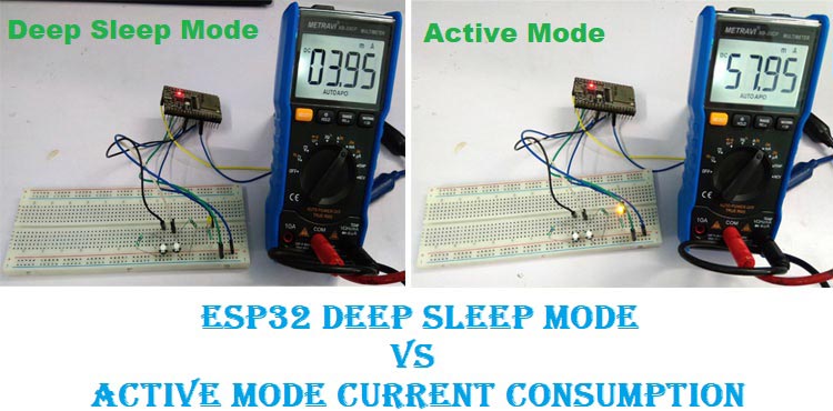
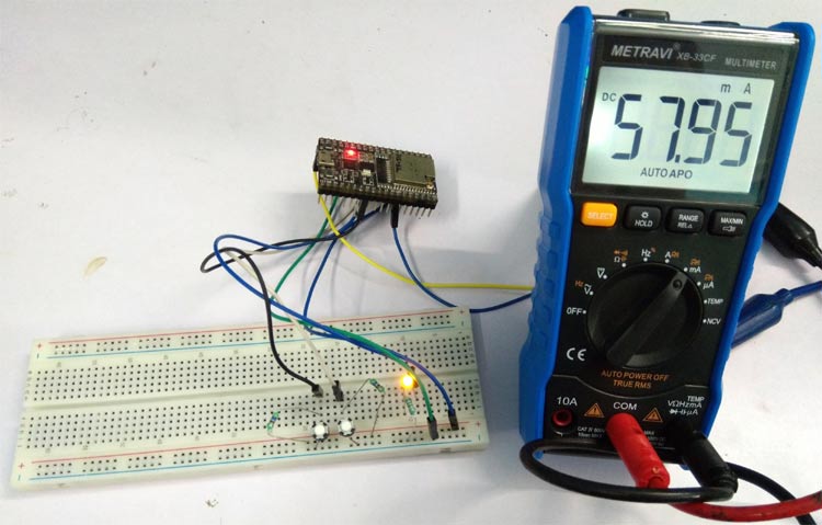
The circuit is constructed in a breadboard and a Metravi XB edition multimeter is used to measure the current. The current drawn by the circuit in active mode is almost 58 mA but in deep sleep mode, the current is almost 4.10 mA. Below image is showing the ESP32 active mode current consumption-
In deep sleep mode, the current consumption is recorded dropped to around 3.95mA, the below image shows the ESP32 Deep Sleep Mode Current Consumption-
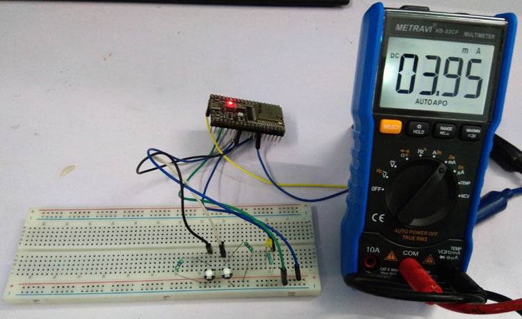
However, in deep sleep mode, ESP32’s current consumption is almost 150 uA. But the recorded current consumption for this ESP32 Devkit board is almost 4.10 mA. This is due to the CP2102 and the Linear Regulator. These two are connected to the 5V power line. There is also a power LED connected in the power line that is consuming almost 2mA of current.
Therefore, it can be easily identified that the ESP32 consumes a very low amount of energy in deep sleep mode condition that is very useful for battery powered operations. For more information on how it worked, check out the video linked below. If you have any questions, leave them in the comment section below or use our Forums for other technical questions.
Complete Project Code
/*
 * File Name: esp32-deep-sleep.ino
 * Created on: 30-Jun-2020
 * Author: Noyel Seth ([email protected])
 */
// create structure for push_button
struct PushBnt{
  const uint8_t pin;
  uint32_t pressCount;
  bool pressed;
};
//Create a PushButton variable
PushBnt pushBtn = {GPIO_NUM_16, 0, false};
// define Led Pin
uint8_t led_pin = GPIO_NUM_4;
// define wake up pin
uint8_t wakeUp_pin = GPIO_NUM_33;
// define taskBlinkled TaskHandle_t variable
TaskHandle_t taskBlinkled;
// define ISR function for PushButtton's Interrupt
void IRAM_ATTR isr_handle() {
  pushBtn.pressed = true;
  pushBtn.pressCount = pushBtn.pressCount + 1;
}
void setup() {
  // put your setup code here, to run once:
  // set the serial port at 115200
  Serial.begin(115200);
  delay(1000);
  // set the pushButton pin as input with internal PullUp
  pinMode(pushBtn.pin, INPUT_PULLUP);
  // set the Interrupt handler with the pushButton pin in Falling mode
  attachInterrupt(pushBtn.pin, isr_handle, FALLING);
  // set the Led pin as ouput
  pinMode(led_pin, OUTPUT);
  //create a task that will be executed in the blinkLed() function, with priority 1 and executed on core 0
  xTaskCreate(
              blinkLed,   /* Task function. */
              "blinkLed",     /* name of task. */
              1024*2,       /* Stack size of task */
              NULL,        /* parameter of the task */
              5,           /* priority of the task */
              &taskBlinkled);      /* Task handle to keep track of created task */
  delay(500);
  //Configure Pin 33 as ext0 wake up source with LOW logic level
  esp_sleep_enable_ext0_wakeup((gpio_num_t)wakeUp_pin, 0);
}
void loop() {
  // put your main code here, to run repeatedly:
   if (pushBtn.pressed) {
      Serial.printf("PushButton(%d) Pressed \n", pushBtn.pin);
      Serial.printf("Suspend the 'blinkLed' Task \n");
      // Suspend the blinkLed Task
      vTaskSuspend( taskBlinkled );
      digitalWrite(led_pin, LOW);
      Serial.printf("Going to sleep..... \n", pushBtn.pin);
      pushBtn.pressed = false;
      //Go to sleep now
      esp_deep_sleep_start();
  }
  esp_sleep_wakeup_cause_t wakeupReason;
  wakeupReason = esp_sleep_get_wakeup_cause();
  switch(wakeupReason)
  {
    case ESP_SLEEP_WAKEUP_EXT0  : Serial.println("using external signal ext0 for WakeUp From sleep"); break;
    case ESP_SLEEP_WAKEUP_EXT1  : Serial.println("using external signal ext1 for WakeUp From sleep"); break;
    case ESP_SLEEP_WAKEUP_TIMER  : Serial.println("using Timer signal for WakeUp From sleep"); break;
    case ESP_SLEEP_WAKEUP_TOUCHPAD  : Serial.println("using TouchPad signal for WakeUp From sleep"); break;
    case ESP_SLEEP_WAKEUP_ULP  : Serial.println("using ULP signal for WakeUp From sleep"); break;
    default : break;
    Serial.printf("Resume the 'blinkLed' Task \n");
    // restart the blinkLed Task
    vTaskResume( taskBlinkled );
  }
}
void blinkLed(void* param){
  while(1){
    static uint32_t pin_val = 0;
    // toggle the pin value
    pin_val ^= 1;
    digitalWrite(led_pin, pin_val);
    Serial.printf("Led ----------------- %s\n" , pin_val? "On" : "Off");
    /* Simply toggle the LED every 1000ms or 1sec */
     vTaskDelay( 1000 / portTICK_PERIOD_MS );
  }
  taskBlinkled = NULL;
  vTaskDelete( NULL );
}

