Gesture control is one of the coolest ways to interact with technology—no buttons, no touchscreens, just simple hand movements. It almost feels like magic when you can control devices with a wave of your hand!
This technology has a wide range of real-world applications, from flying drones and controlling robots to managing smart home devices and even assisting individuals with disabilities. Instead of pressing buttons or using voice commands, you can simply move your hand in a specific way to send instructions. In fact, we have previously built many gesture control projects which you can take a look at if you are interested.
In this ESP32 project, we’ll build a simple ESP32 air mouse using an MPU6050 sensor and an ESP32. The MPU6050 will track hand movements in real time, and the ESP32 will process the data and send it wirelessly via Bluetooth or Wi-Fi, making it easy to control various devices. We will demo this project by using Processing to move a ball around the screen, but you can use it for a variety of applications.
Table of Contents
- Overview of the Hand Gesture Control Device
- Components Required
- Circuit Connection of the Gesture Control Device
- Code for Gesture Control Device
- └ Libraries Used
- └ Variables and Constants
- └ Loop Function
- └ Supportive Functions
- Working of Hand Gesture Recognition Device
- GitHub Repository with Code and Circuit
- DIY Projects Using Gesture Recognition
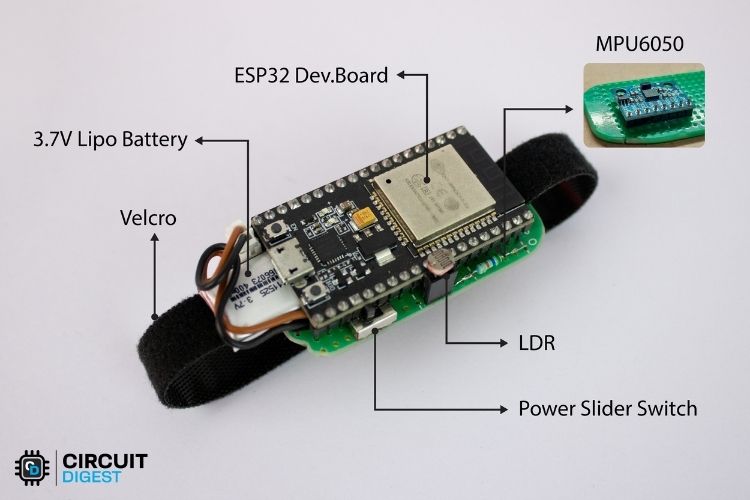
ESP32 Mouse - Overview
This project focuses on building a hand gesture control device using an ESP32 and an MPU6050 sensor. The MPU6050 acts as the primary sensor, detecting movements along the X and Y axes similar to how the mouse tracks the movement of a cursor on X and Y axes. Additionally, an LDR is included to act like a mouse click. If you are completely new to MPU6050, do check out our tutorial on how to use MPU6050 with ESP32.
The core idea is to use this device to control the movement of objects that operate in an X-Y plane. For example, you can use hand gestures to steer an RC car, control a drone, or navigate robotic systems effortlessly.
Unlike traditional control methods that rely on buttons, joysticks, or voice commands, gesture-based control offers a more intuitive and immersive experience. The accelerometer and gyroscope inside the MPU6050 track hand movements with precision. The ESP32 then processes this data, applies a Kalman filter for smoother motion tracking, and transmits the information wirelessly via Bluetooth or Wi-Fi to the controlled device.
Components Required
Since we are making a basic gesture control system, the features are kept simple. However, you can modify it based on your requirements and budget. Unlike other projects, you are not limited to the component list below.
Necessary Components
ESP32 Development Board - 1
MPU6050 Module - 1
LDR (Light Dependent Resistor) - 1
Resistor 56kΩ - 1
LiPo Battery - 1
Perfboard - As per requirement
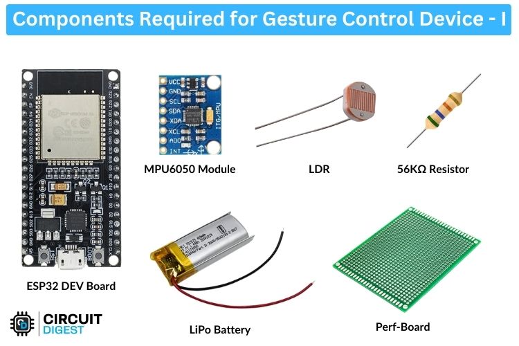
The ESP32 Development Board has multiple variants. You can use any one, but GPIO pin positions may differ, so ensure you are using the correct ones. Similarly, for the MPU6050 module, different variants exist, so use the correct pinout connections.
Regarding the battery, it depends on your needs. Factors like runtime, space availability, and budget determine the choice. In my case, I'm using a small LiPo battery that fits inside the bottom of the ESP32 board, sacrificing some runtime for a compact design.
Optional Components
Power Switch (SPDT Slide Switch) – 1
Velcro Ties – As per requirement
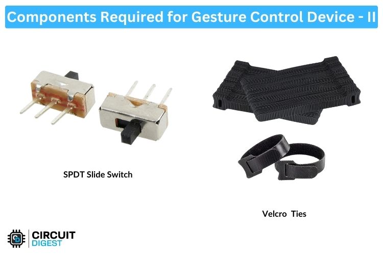
The SPDT slide switch is used to turn the circuit on and off, while the Velcro Ties help secure the device to your hand for comfortable use. Next, let's move on to the interesting part—the circuit connections.
Circuit Diagram
Due to its minimal features and components, the circuit connection is quite simple. Below, you can see the schematic for understanding the circuit connection in the gesture control device.

The schematic is self-explanatory, meaning there is nothing complex. Starting from the power supply, I am connecting the LiPo battery directly to the 5V rail of the ESP32 development board. This is because there is an LDO, like the AMS1117-3.3, whose primary duty is to regulate the input voltage to 3.3V, which is then fed to the ESP32. So, providing a 4.2V max LiPo battery is normal for this operation and can be directly connected to the 5V rail of the ESP32. Since I wanted to make it switchable, I added a switch, which is an SPDT slide switch.
Next is the LDR circuit, which consists of a 56K resistor. Here, the resistor and the LDR in combination create a traditional voltage divider circuit. To put it briefly, the LDR’s resistance changes with variations in light intensity. When the resistance of one side of the voltage divider changes, the output voltage also changes. This varying voltage is then fed to the ADC of the ESP32 and serves as an input signal. In our case, since the LDR is placed inside our hand, it produces a value of 1 in darkness (when covered) and 0 when exposed to more light (when the hand is open). This can be used to turn the controllable device on and off.
Next, the MPU6050’s SCL and SDA pins are connected to the I2C pins of the ESP32, which are GPIO21 (SDA) and GPIO22 (SCL). It is powered using the ESP32’s 3.3V supply.
So, now we have a clear understanding of the schematic.
Now, Let's Assemble the Circuit
ESP32 Air Mouse Hardware Assembly
In this project, the trickiest part is assembling the circuit, specifically, connecting the components together. The goal is to achieve the smallest form factor possible to ensure the device can be comfortably held in hand. I'll show my method, but there are many ways to improve the design even further.
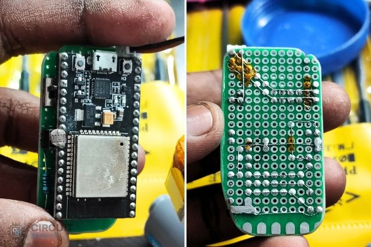
Step 1: Preparing the Perfboard
Keeping in mind the need for a minimal form factor and comfortable placement, I cut down the required size of the perfboard from a larger one. After cutting, I used a file set to smooth the corners, making it easier and more comfortable to hold in my hand.
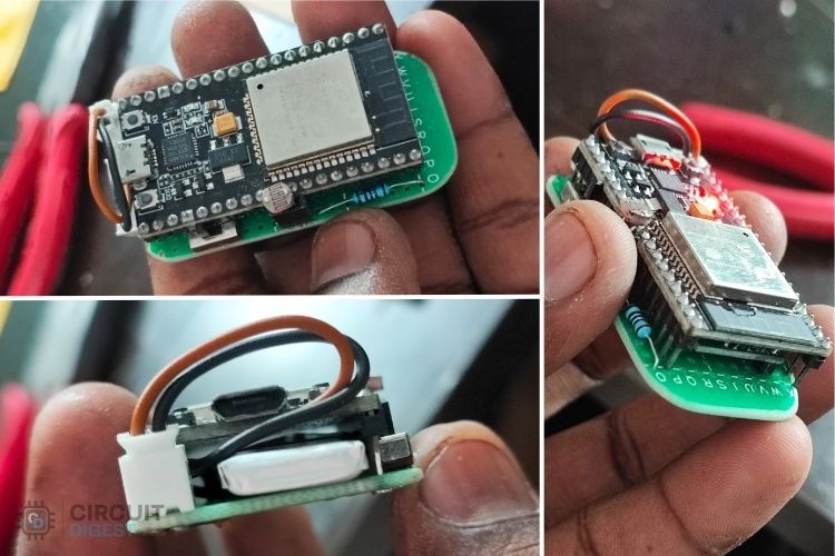
Step 2: Component Placement
After completing the filing, it was time for component placement. First, I placed the MPU6050 at the bottom of the ESP32 development board to optimize space. I also ensured there was some space below the MPU6050, as it would later be used for inserting a Velcro tie.
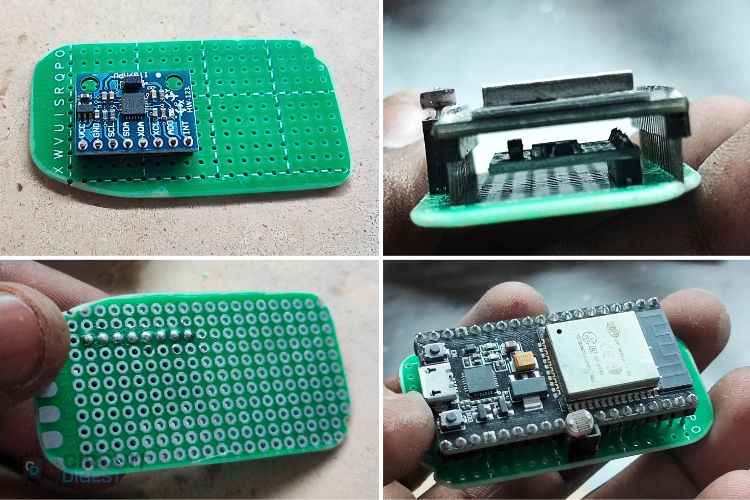
As seen in the above image, I positioned the MPU6050 directly below the ESP32. Additionally, I placed the LDR at the side of the ESP32. You may also notice that the ESP32 module is raised significantly, creating space underneath. This space was later used to insert the LiPo battery.
Step 3: Soldering the Components
After completing the assembly, I started the soldering process. This step was a bit tricky due to the compact form factor and the need to ensure holding comfort. Using regular-sized solder joints might have affected the compactness, so I chose a custom approach.
I removed individual strands from a wire and handcrafted small-sized connecting wires to maintain a neat and compact structure. The image below shows how this was done.
Since I used bare strands without insulation, crossing two wires was a bit challenging. To solve this, I used Kapton tape, which worked perfectly.
Step 4: Powering the Circuit
After carefully completing all the circuit connections, it was time to connect the power input.
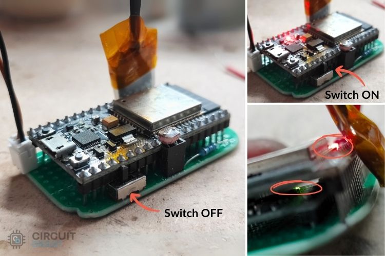
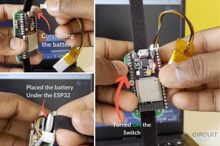
As shown above, I inserted the LiPo battery and turned on the power. Everything worked fine without any issues.
After a final check, I securely placed the battery below the ESP32 module. Below, you can see the fully assembled device.
Next step is to code the device.
Arduino Code for ESP32 AirMouse
This code reads acceleration and gyroscope data from an MPU6050 sensor and applies a Kalman filter to smooth and correct the readings. It also reads ambient light levels using an LDR sensor and transmits the processed data wirelessly via Bluetooth. The code also continuously sends filtered sensor data over serial for debugging purposes.
Let's understand the code!
Libraries Used
Adafruit_MPU6050.h - Handles communication with the MPU6050 sensor.
Adafruit_Sensor.h - Provides a common interface for sensor data.
Wire.h - Enables I2C communication with the sensor.
BluetoothSerial.h - Allows data transmission over Bluetooth.
Variables and Constants
Library Objects:
Adafruit_MPU6050 mpu; - Object to interact with the MPU6050 sensor.
BluetoothSerial SerialBT; - Object for Bluetooth communication.
Pin Definitions:
const int LDRSensor = 34; - GPIO pin connected to the LDR sensor
Kalman Filter Parameters:
float x_angle, y_angle; - Stores filtered angle estimates.
float x_bias, y_bias; - Stores gyroscope bias correction.
float P[2][2] = { { 1, 0 }, { 0, 1 } }; - Error covariance matrix
Tuning parameters:
float q_angle = 0.01; - Trust in angle estimates.
float q_bias = 0.01; - Trust in gyroscope bias correction.
float r_measure = 0.01; - Trust in sensor readings.
These values can be adjusted to change the responsiveness and smoothness of the Kalman filter.
Setup Function
void setup() {
 Serial.begin(115200);  // Initialize Serial Monitor
 SerialBT.begin("ESP32_BT");  // Initialize Bluetooth with device name "ESP32_BT"
 // Initialize MPU6050 sensor
 if (!mpu.begin()) {
   Serial.println("MPU6050 not found!");
   while (1) delay(10);  // Halt execution if MPU6050 is not detected
 }
 // Set MPU6050 configuration
 mpu.setAccelerometerRange(MPU6050_RANGE_8_G);  // Set accelerometer range
 mpu.setGyroRange(MPU6050_RANGE_500_DEG);       // Set gyroscope range
 mpu.setFilterBandwidth(MPU6050_BAND_10_HZ);    // Apply a low-pass filter
 delay(100);  // Allow settings to take effect
}
Initializes serial communication at 115200 baud for debugging.
Starts Bluetooth communication with the device name "ESP32_BT".
Initializes the MPU6050 sensor and verifies its presence.
Configures the MPU6050 sensor:
Sets the accelerometer range to ±8g.
Sets the gyroscope range to ±500°/s.
Applies a low-pass filter with a 10 Hz bandwidth.
Delays briefly to allow configurations to take effect.
Loop Function
void loop() {
 sensors_event_t a, g, temp;  // Variables to store sensor readings
 mpu.getEvent(&a, &g, &temp); // Get sensor data
 int ldrValue = analogRead(LDRSensor);  // Read LDR sensor value
 int outputValue = (ldrValue < 2000) ? 0 : 1;  // Determine light or dark condition
 static unsigned long prevTime = millis();
 float dt = (millis() - prevTime) / 1000.0;  // Convert to seconds
 prevTime = millis();
 float filteredX = kalmanFilter(a.acceleration.x, g.gyro.x, dt, x_angle, x_bias);
 float filteredY = kalmanFilter(a.acceleration.y, g.gyro.y, dt, y_angle, y_bias);
 String btData = String(filteredX, 2) + "," + String(filteredY, 2) + "," + String(outputValue);

 SerialBT.println(btData);
 Serial.println(btData);
}
Reads acceleration and gyroscope data from the MPU6050.
Reads ambient light levels from the LDR sensor.
Computes the time difference (dt) since the last loop iteration.
Applies the Kalman filter to smooth accelerometer and gyroscope readings.
Formats the filtered data into a string for Bluetooth transmission.
Sends the data wirelessly over Bluetooth and also prints it to the serial monitor for debugging.
Optionally delays slightly to stabilize the loop execution.
Supportive Functions
float kalmanFilter(float newAngle, float newRate, float dt, float &angle, float &bias);
Implements the Kalman filter to process raw sensor data.
Corrects gyroscope drift and noise in the readings.
Returns the refined angle estimate.
float kalmanFilter(float newAngle, float newRate, float dt, float &angle, float &bias) {
 float rate = newRate - bias;  // Remove bias from gyroscope rate
 angle += dt * rate;  // Estimate new angle
 // Update estimation error covariance
 P[0][0] += dt * (dt * P[1][1] - P[0][1] - P[1][0] + q_angle);
 P[0][1] -= dt * P[1][1];
 P[1][0] -= dt * P[1][1];
 P[1][1] += q_bias * dt;
 // Compute Kalman gain
 float S = P[0][0] + r_measure;
 float K[2] = { P[0][0] / S, P[1][0] / S };
 // Update estimates with measurement
 float y = newAngle - angle;
 angle += K[0] * y;
 bias += K[1] * y;
 // Update error covariance matrix
 P[0][0] -= K[0] * P[0][0];
 P[0][1] -= K[0] * P[0][1];
 P[1][0] -= K[1] * P[0][0];
 P[1][1] -= K[1] * P[0][1];
 return angle;  // Return the filtered angle
}
With this, the coding part is completed. For the full code, refer below.
Testign and Working
After successfully uploading the code, let's perform a quick test. But you might wonder, how can we make this testing more effective? We have improved it with the help of a Processing program.
This Processing program visualizes real-time data received via a serial connection, likely from an Arduino. It maps incoming X and Y values to screen coordinates and displays a ball that changes color based on a sensor value.
Key features of the Processing program include real-time visualization of sensor data, a dynamic gradient background, cross lines marking the center for reference, a glowing effect for enhanced visuals, and live data display for better debugging.
This makes the demonstration more engaging and interactive. You can find the complete Processing code in our GitHub repository.
First, let's set up the device.
Step 1: Powering and Pairing the Device
To start the test,
Turn on the device using the switch.
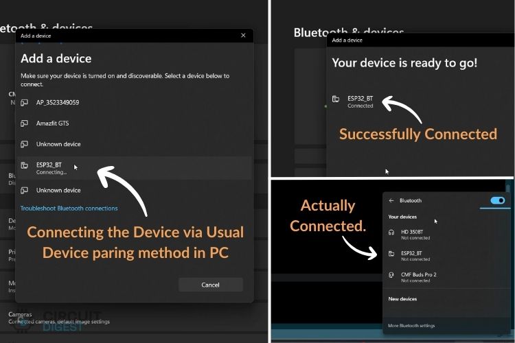
Now, pair the device with the PC via Bluetooth. Above, you can see the pairing steps.
Once the pairing is complete, we are ready to receive data.
Important Note: Windows provides better Bluetooth compatibility than Mac for this project. In Windows, even if it shows "Not Connected", the device is actually connected and can transfer data successfully.
Step 2: Running the Processing Code
Open the Processing IDE and run this Processing code. If this is your first time using Processing, do not worry it is a very easy-to-use programming platform that is similar to Arduino. We have previously built many projects using processing, you can also check them out.
At first, you might see a connection error because you need to select the correct communication port.
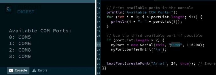
When you run the Processing code, it will display a list of available COM ports.
You may need to use trial and error to find the correct one.
In my case, the correct COM port is COM8.
Step 3: Viewing the Data Output
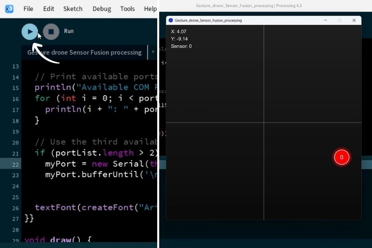
On pressing the Run button, a small window created by Processing will show the real-time movement of the device.
At this point, you can test the functionality of the device.
You may need to adjust the X and Y values to ensure everything is working correctly.
The ball on the Processing screen should respond to hand gestures in real time.
With this, the gesture control device is now fully functional and ready for further testing or real-world applications.
Above, you can see a small working video for better visualization of the device in action.
GitHub Repository with Code and Circuit


Other Gesture Control Projects
Explore a variety of gesture-controlled projects ranging from controlling media players to robots. Each project demonstrates simple ways to use hand gestures for contactless control and accessibility.

Hand Gesture Recognition using ESP32 and Python
Learn how to control LEDs using hand gestures with ESP32 and Python. This beginner-friendly project uses OpenCV and MediaPipe for real-time gesture recognition and IoT-based device control.

Gesture Controlled Robot Using Arduino
Build a gesture-controlled robot using Arduino and an accelerometer sensor. This DIY project lets you control robot movement with hand gestures.

Arduino based Gesture controlled Robot using Accelerometer
Learn how to build a gesture-controlled robot designed to assist individuals with disabilities. This Arduino-based project uses hand gestures for seamless, touch-free control.

Control your Computer with Hand Gestures using Arduino
Discover how to control your computer using simple hand gestures in this project. Learn to combine Python with Arduino and an accelerometer for hands-free PC interaction.

Gesture based Intelligent Appliance Control Robot
Build a gesture-based intelligent appliance control system using Arduino and an accelerometer. Learn how to automate home devices with simple hand gestures for smarter living.

Create a gesture-controlled media player using Raspberry Pi and MediaPipe. Control your music and videos with hand gestures in this project.

Gesture Controlled Contactless Elevator using APDS9960 Sensor
Build a gesture-based contactless elevator system using Arduino and the APDS9960 sensor. Enhance hygiene and user experience with this smart automation project.

Hand Gesture Recognition using Raspberry Pi and OpenCV
Learn how to build a hand gesture recognition system using Raspberry Pi and OpenCV. Detect and track hand movements for smart automation and control.
Complete Project Code
/*
Features:
 - Reads acceleration and gyroscope data from an MPU6050 sensor.
 - Uses a Kalman filter to smooth and correct sensor readings.
 - Reads ambient light levels using an LDR sensor.
 - Communicates sensor data wirelessly via Bluetooth.
 - Sends processed values over serial for debugging.
 Applications:
 - Motion tracking and gesture recognition.
 - Balancing robots and stabilization systems.
 - Smart lighting systems based on ambient light levels.
 - Wearable motion analysis and health tracking.
 - Wireless remote control based on tilt movements.
*/
#include <Adafruit_MPU6050.h>
#include <Adafruit_Sensor.h>
#include <Wire.h>
#include "BluetoothSerial.h"
Adafruit_MPU6050 mpu;  // Create MPU6050 sensor object
BluetoothSerial SerialBT;  // Create Bluetooth serial object
const int LDRSensor = 34;  // Define the LDR sensor pin
// Kalman filter variables
float x_angle = 0, y_angle = 0; // Filtered angle estimates
float x_bias = 0, y_bias = 0;   // Gyroscope bias correction
float P[2][2] = { { 1, 0 }, { 0, 1 } };  // Error covariance matrix
// Kalman filter tuning parameters
// Adjust these for different levels of noise filtering and responsiveness
// Quick and Less Smooth Response
float q_angle = 0.01;    // Trust new angle estimates more
float q_bias = 0.01;     // Faster correction of gyroscope drift
float r_measure = 0.01;  // Trust sensor readings more (less smoothing)
// // Alternative: Optimum Response
// const float q_angle = 0.001; // Process noise
// const float q_bias = 0.003;
// const float r_measure = 0.03; // Measurement noise
// // Alternative: Slow and smooth response
// float q_angle = 0.0001;   // Trust new angle estimates more
// float q_bias = 0.0005;    // Faster correction of gyroscope drift
// float r_measure = 0.05;   // Trust sensor readings more (less smoothing)
void setup() {
 Serial.begin(115200);  // Initialize Serial Monitor
 SerialBT.begin("ESP32_BT");  // Initialize Bluetooth with device name "ESP32_BT"
 // Initialize MPU6050 sensor
 if (!mpu.begin()) {
   Serial.println("MPU6050 not found!");
   while (1) delay(10);  // Halt execution if MPU6050 is not detected
 }
 // Set MPU6050 configuration
 mpu.setAccelerometerRange(MPU6050_RANGE_8_G);  // Set accelerometer range
 mpu.setGyroRange(MPU6050_RANGE_500_DEG);       // Set gyroscope range
 mpu.setFilterBandwidth(MPU6050_BAND_10_HZ);    // Apply a low-pass filter
 delay(100);  // Allow settings to take effect
}
// Kalman filter function to smooth sensor data
float kalmanFilter(float newAngle, float newRate, float dt, float &angle, float &bias) {
 float rate = newRate - bias;  // Remove bias from gyroscope rate
 angle += dt * rate;  // Estimate new angle
 // Update estimation error covariance
 P[0][0] += dt * (dt * P[1][1] - P[0][1] - P[1][0] + q_angle);
 P[0][1] -= dt * P[1][1];
 P[1][0] -= dt * P[1][1];
 P[1][1] += q_bias * dt;
 // Compute Kalman gain
 float S = P[0][0] + r_measure;
 float K[2] = { P[0][0] / S, P[1][0] / S };
 // Update estimates with measurement
 float y = newAngle - angle;
 angle += K[0] * y;
 bias += K[1] * y;
 // Update error covariance matrix
 P[0][0] -= K[0] * P[0][0];
 P[0][1] -= K[0] * P[0][1];
 P[1][0] -= K[1] * P[0][0];
 P[1][1] -= K[1] * P[0][1];
 return angle;  // Return the filtered angle
}
void loop() {
 sensors_event_t a, g, temp;  // Variables to store sensor readings
 mpu.getEvent(&a, &g, &temp); // Get sensor data
 int ldrValue = analogRead(LDRSensor);  // Read LDR sensor value
 int outputValue = (ldrValue < 2000) ? 0 : 1;  // Determine light or dark condition
 // Calculate time difference for Kalman filter
 static unsigned long prevTime = millis();
 float dt = (millis() - prevTime) / 1000.0;  // Convert to seconds
 prevTime = millis();
 // Apply Kalman filter to smooth sensor data
 float filteredX = kalmanFilter(a.acceleration.x, g.gyro.x, dt, x_angle, x_bias);
 float filteredY = kalmanFilter(a.acceleration.y, g.gyro.y, dt, y_angle, y_bias);
 // Format data for Bluetooth transmission
 String btData = String(filteredX, 2) + "," + String(filteredY, 2) + "," + String(outputValue);
 // Send data over Bluetooth and Serial for debugging
 SerialBT.println(btData);
 Serial.println(btData);
 // Small delay to stabilize loop execution
 // delay(1); // Uncomment if needed
}