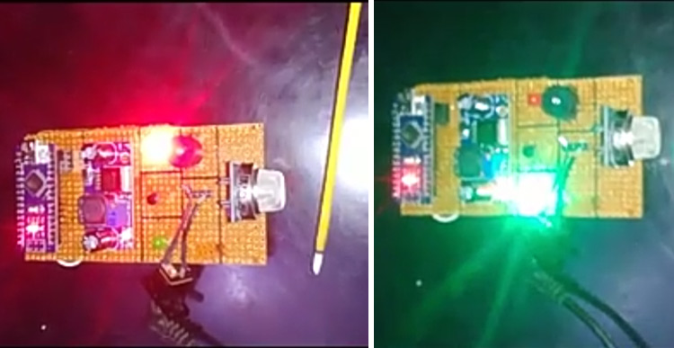
A gas detector is a device that detects the presence of gases in an area, often as part of a safety system. This type of equipment is used to detect a gas leak or other emissions and can interface with a control system so a process can be automatically shut down. A gas detector can sound an alarm to operators in the area where the leak is occurring, giving them the opportunity to leave. This type of device is important because there are many gases that can be harmful to organic life, such as humans or animals. Gas detectors can be used to detect combustible, flammable, and toxic gases and oxygen depletion. My inspiration to build this device is to give an alert of a gas leak before it affects human life. Due to gas leaks and blasts, many of them lost their life.
Also check our previous project based on Gas sensor- Fire Alarm with GSM, Gas Detector with MQ3 Gas Sensor.
Features
- Detection and prevention of any sort of gas leakage
- Cost-efficient
- Less complex circuit In the future, my plan is to make advancements in this leak detector as it works well.
Component Requirement for Gas Leak Alert System

Project Used Hardware
- Arduino Nano R3,
- LPG Gas Sensor (MQ5),
- 5 mm LED: Green,
- 5 mm LED: Red,
- Buzzer,
- 5V 2.5A Switching Power Supply
Project Used Software
- Arduino IDE
Project Hardware Software Selection
Arduino Nano:- The Arduino Nano is a small, complete, and breadboard-friendly board based on the ATmega328 (Arduino Nano 3. x). It has more or less the same functionality as the Arduino Duemilanove but in a different package. It lacks only a DC power jack and works with a Mini-B USB cable instead of a standard one. It works as the brain of the whole system.
MQ5 Gas Sensor:- Gas Sensor(MQ5) module is useful for gas leakage detection (in home and industry). It is suitable for detecting H2, LPG, CH4, CO, Alcohol. Due to its high sensitivity and fast response time, measurements can be taken as soon as possible.
Buzzer:- This is used to alert the surroundings about gas leaks.
LED:- It works as an indicator.
Circuit Diagram
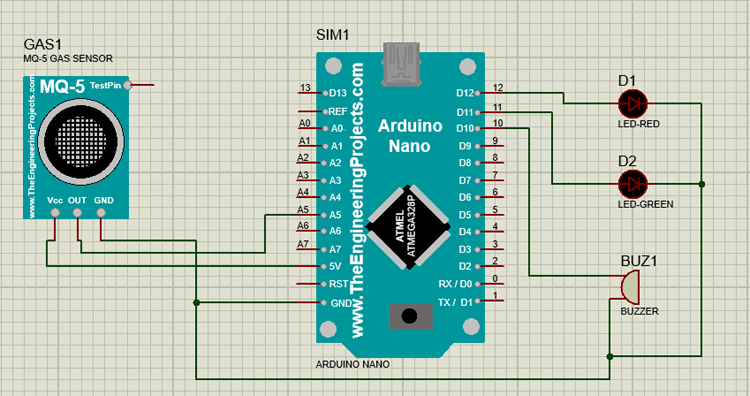
In this project, I am using an mq5 gas detector sensor with Arduino Nano. The voltage that the sensor outputs changes accordingly to the smoke/gas level that exists in the atmosphere. The sensor outputs a voltage that is proportional to the concentration of smoke/gas. When LPG gas leakage is sensed, it will give a HIGH pulse on its DO pin and Arduino constantly reads its DO pin. When Arduino receives a HIGH pulse from the LPG Gas sensor module its green led turns off and the red LED turns on with led a 5v buzzer also starts beeping until it senses LPG gas. When Arduino gets a LOW pulse from the LPG Gas detector module, then the red led and buzzer turns off and the green led turns on.
Complete Project Code
int redLed = 12;
int greenLed = 11;
int buzzer = 10;
int smokeA0 = A5;
// Your threshold value
int sensorThres = 120;
void setup() {
  pinMode(redLed, OUTPUT);
  pinMode(greenLed, OUTPUT);
  pinMode(buzzer, OUTPUT);
  pinMode(smokeA0, INPUT);
  Serial.begin(9600);
}
void loop() {
  int analogSensor = analogRead(smokeA0);
  Serial.print("Pin A0: ");
  Serial.println(analogSensor);
  // Checks if it has reached the threshold value
  if (analogSensor > sensorThres)
  {
    digitalWrite(redLed, HIGH);
   digitalWrite(greenLed, LOW);
    digitalWrite(buzzer, HIGH);
  }
  else
  {
    digitalWrite(redLed, LOW);
    digitalWrite(greenLed, HIGH);
    digitalWrite(buzzer, LOW);
  }
  delay(100);
}


