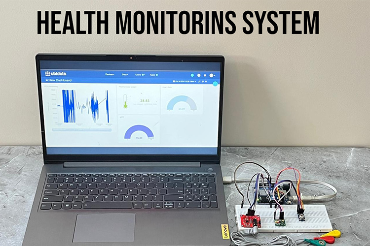
This project facilitates real-time remote monitoring of critical health metrics such as heart rate, SpO2, body temperature, and ECG data, which could benefit both patients and healthcare providers. By enabling continuous data transmission to Ubidots, this system provides an accessible and scalable solution for remote health monitoring, which can be particularly beneficial in areas with limited healthcare infrastructure or during emergencies when timely data collection and response are crucial.
With its use of IoT and MQTT protocols, this solution demonstrates how affordable microcontrollers and sensors can be leveraged for real-world health applications. The project supports advancements in remote diagnostics, preventive healthcare, and personalized health monitoring, potentially reducing hospital visits and healthcare costs while improving patient outcomes.
I used Fritzing to create the circuit diagram. For power input, I am using a 2S Li-ion battery pack, which provides an average voltage of 7.4V. This is connected to the Vin pin of the Arduino UNO Board.
Components And Their Functions:
Role: Acts as the central microcontroller of the system.
Functions: Processes data from various sensors, handles communication with the Blink app, and manages real-time data collection and alert notifications.
2. AD8232 ECG Heart Rate Monitor Sensor Module:
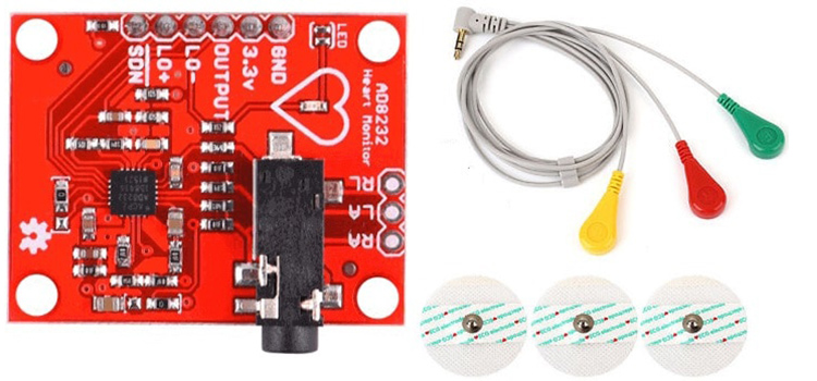
Role: Measures the electrical activity of the heart.
Functions: ECG or Electro CardioGraphy is a method to measure some important parameters of a human heart. It outputs analog values that produce a particular signal that looks as shown below.
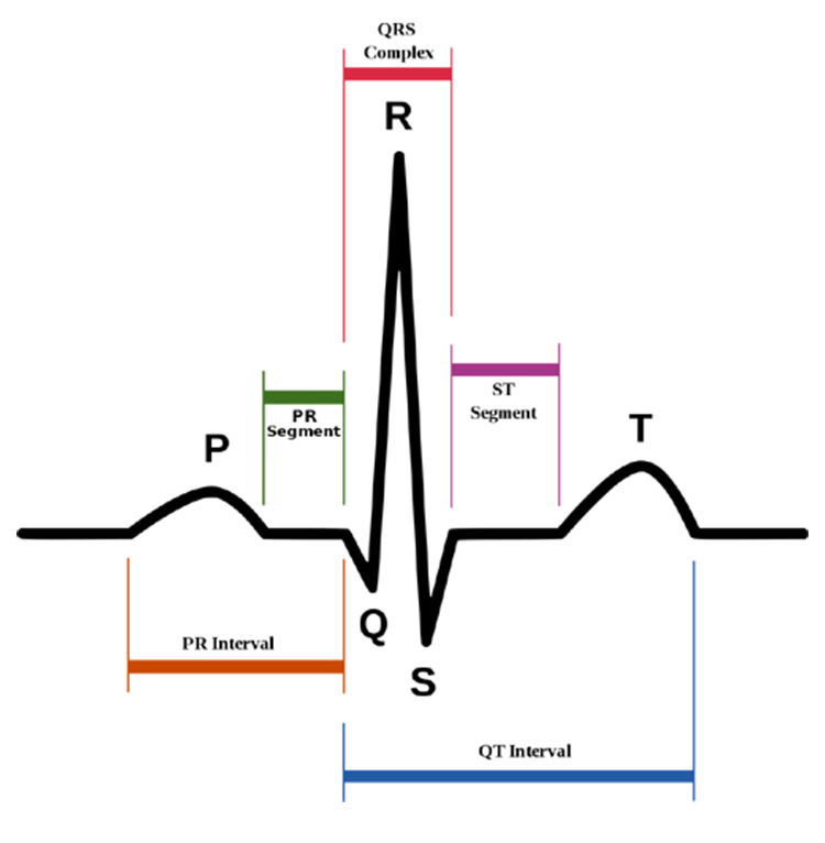
As visible, the signal has a few peaks and important features that are of biological importance. These are marked below.
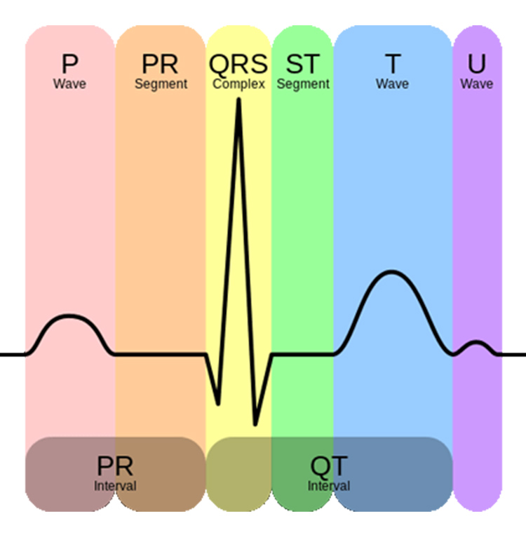
Each interval has an optimal value range, and deviation from that might be linked to a particular disease. Here are the main parts of an ECG signal.
P wave - It is the trailing wave on the left of the QRS complex.
QRS complex - It is an impulse generated by ventricular contraction.
T wave - It is a leading wave right to the QRS complex.
U wave - It is not always observed due to its low peak value.
There are many other features as well, but these are the main ones. Based on the shapes of the above features, their interval as well as the interval between them, we can diagnose a lot of cardiac diseases and irregularities. For example:
Irregular heartbeat or absence of P-wave: Atrial Fibrillation
Resting Heart Rate of more than 100: Tachyarrhythmia
Tachyarrhythmia and delta wave: Wolf-Parkinson-White or WPW syndrome
Sawtooth P wave: Atrial flutter
Depression of ST-segment: it might indicate Ischemia
Elevation of ST-segment: it might indicate myocardial Infarction
Hence, ECGs are extremely important for a cardiologist or any doctor for that matter.
Today, we will try to develop a simple system that will be able to measure ECG signal values and even measure the heartbeat of a person using them. First, we will focus on the hardware part as to how exactly is the ECG signal retrieved from the human body?
AD8232 ECG Sensor Electrodes Placement (3 Lead Sensor)
The AD8232 ECG sensor is the most commonly used and available ECG sensor that is affordable and can be used for hobby purposes. It is a 3 lead or single-channel ECG module. Other ECG sensor types available are 5 lead and 10 lead. Visit this link for more details about ECG positioning: https://litfl.com/ECG-lead-positioning/
For a 3-lead system, there are two placements that are used-
For a 3-lead system, there are two placements that are used-
Electrode Name
Electrode colour
Location
RA
Red
Right Arm
LA
Yellow
Left Arm
RL
Green
Right Leg
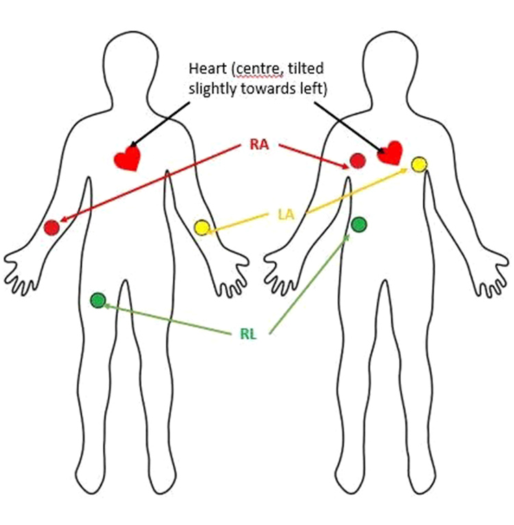
The left position is generally used for females and is the reason why the three electrodes are called RA, LA, and RL. However, this method of placing electrodes produces more noise and hence, it is preferred that the electrodes are placed as shown in the right position, especially for hospital patients.
Connections:
AD8232 LO- to Arduino 7
AD8232 LO+ to Arduino 6
AD8232 OUT to Arduino Analog Input (e.g., A5)
AD8232 3.3V to Arduino 3.3V
AD8232 GND to Arduino GND
3. MLX90614 Temperature Sensor Module:
Role: Measures body temperature.
Functions: Provides accurate temperature readings to detect fever or other temperature-related health issues.
Connections:
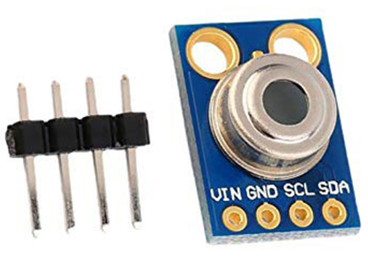
MLX90614 VCC to Arduino 5V
MLX90614 GND to Arduino GND
MLX90614 SDA to Arduino SDA (SDA pin for I2C)
MLX90614 SCL to Arduino SDA (SCL pin for I2C)
4. MAX30102 Pulse Oximeter and Heart Rate Sensor:
Role: Measures blood oxygen saturation (SpO2) and heart rate.
Functions: Uses light-based technology to determine oxygen levels in the blood and heart rate, critical for assessing respiratory and cardiovascular health.
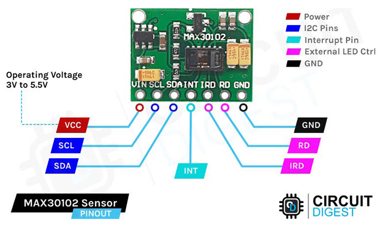
Connections:
MAX30102 VCC to Arduino 3.3V
MAX30102 GND to Arduino GND
MAX30102 SDA to Arduino SDA (SDA pin for I2C)
MAX30102 SCL to Arduino SCL (SCL pin for I2C)
5. Connecting Jumper Wires:
Role: Facilitate connections between the sensors and the Arduino.
Functions: Ensure proper electrical connections for data transmission between components.
6. Power Supply (2S Li-ion battery pack or any power supply between 6V - 24V DC):
Role: Provides the necessary power to the entire system.
Functions: Ensures the system remains operational and portable, especially important for wearable or mobile health monitoring setups.
How It All Comes Together:
Data Collection:
The ECG sensor (AD8232) continuously monitors the heart’s electrical activity, detecting anomalies.
The MLX90614 temperature sensor tracks body temperature, alerting to potential fever or temperature changes.
The MAX30102 pulse oximeter measures both blood oxygen levels and heart rate, providing insights into respiratory and cardiovascular health.
2. Data Processing:
The Arduino Uno R4 WiFi collects data from all the sensors.
It processes this data to generate meaningful health metrics. For example, it can calculate heart rate variability from ECG signals or determine average SpO2 levels from multiple readings.
3. Real-Time Monitoring and Alerts:
The Arduino sends the processed data to the Blink app via its WiFi capabilities.
The Blink app provides real-time monitoring of health metrics, enabling remote observation.
If any health parameters fall outside of predefined thresholds (e.g., abnormally high heart rate or low SpO2), the system can trigger alerts to both the patient and healthcare providers.
4. Remote Access and Management:
The Blink app enables users to view their health data remotely, reducing the need for frequent in-person visits to healthcare facilities.
Healthcare providers can access the data to make informed decisions and intervene when necessary, improving patient outcomes through proactive care.
5. Adaptability and Scalability:
The modular design allows for easy upgrades and integration of additional sensors or features as technology advances.
This adaptability ensures the system can be customized for different healthcare needs and patient profiles.
Above, you can see the assembled image of the components. With the connections completed, let's move on to coding the Arduino board.
Code Explanation
This code is designed for an Arduino UNO R4 WiFi microcontroller to collect physiological data (heart rate, SpO2, body temperature, and ECG) using multiple sensors, then send that data to Ubidots, an IoT platform, via Wi-Fi using MQTT (Message Queuing Telemetry Transport). Here’s a breakdown:
Libraries And Configuration
1.Libraries:
Wire:For I2C communication (used by some sensors).MAX30100_PulseOximeter:To communicate with the MAX30100 pulse oximeter sensor.Adafruit_MLX90614:To interact with the MLX90614 temperature sensor.WiFiS3:To handle Wi-Fi communication.PubSubClient:To send data to the Ubidots MQTT broker.
Constants:
WIFISSID, PASSWORD:Credentials for Wi-Fi connection.TOKEN:Ubidots API token for authorization.DEVICE_LABEL and VARIABLE_LABEL_*:Labels used in Ubidots to identify this device and its data variables.MQTT_CLIENT_NAME:Unique name for the MQTT client.ECG_PIN:Analog pin where the ECG sensor (AD8232) is connected.REPORTING_PERIOD_MS:Interval (1000 ms) between each data upload to Ubidots.
Objects And Variables
Sensor Objects:
PulseOximeter pox:Interface object for the MAX30100.Adafruit_MLX90614 mlx:Interface object for the MLX90614.
WiFi and MQTT Objects:
WiFiClient espClient:Used for Wi-Fi communication.PubSubClient client:Used for MQTT communication with Ubidots.
Data Buffers:
topic and payload: Used to store MQTT topic and JSON payload data.
Functions
Setup_wifi()
This function connects the ESP32 to Wi-Fi.
Prints Wi-Fi status in the Serial Monitor.
Checks the connection status every second, printing dots (".") until successfully connected.
Once connected, it displays the IP address.
Reconnect()
This function reconnects to the MQTT broker if disconnected.
Attempts to connect with
client.connect()usingMQTT_CLIENT_NAMEandTOKENfor authentication.If the connection fails, it waits 2 seconds before retrying.
OnBeatDetected()
Callback function executed each time a heartbeat is detected by the MAX30100, printing "Beat Detected!" to the Serial Monitor.
Setup()
This is the main setup function for the program.
1.Serial Communication: Starts Serial for data output to the monitor.
2.Wi-Fi Setup: Calls setup_wifi() to establish Wi-Fi connection.
3.MQTT Setup: Configures Ubidots as the MQTT server at industrial.api.ubidots.com on port 1883.
4.Sensor Initialization:
Initializes the MAX30100 pulse oximeter and sets the IR LED current.
Initializes the MLX90614 temperature sensor.
Sets the ECG pin (A0) as an input.
Loop()
This function contains the main code loop, running continuously.
MQTT Reconnection: Calls
reconnect()if the MQTT client is disconnected.MAX30100 Update: Reads and processes data from the MAX30100 for heart rate and SpO2.
ECG Reading: Reads the analog ECG signal from the AD8232 connected to A0.
Data Reporting:
Every 1000 ms, retrieves sensor data:
Heart Rate and SpO2: Reads heart rate and SpO2 values from the MAX30100.
Temperature: Reads ambient and object temperatures from the MLX90614.
ECG Value: Analog reading from ECG sensor.
Prints all values to the Serial Monitor.
5. Payload Creation and Publishing:
Constructs a JSON payload with the sensor data.
Publishes the data to Ubidots via MQTT.
6. Timestamp Update: Updates the tsLastReport timestamp to control the reporting interval.
This setup continuously gathers sensor data and uploads it to Ubidots for real-time monitoring.
Next, let's upload the code (provided in the code section) and see how it works.
Working Demonstration
After uploading the code to the Arduino UNO R4 WiFi board, I turned on the hotspot and waited for the system to connect to the network. After some time, it connected successfully and began updating the fields in the Ubidots Cloud dashboard.
Below, you can see the working image of the project.
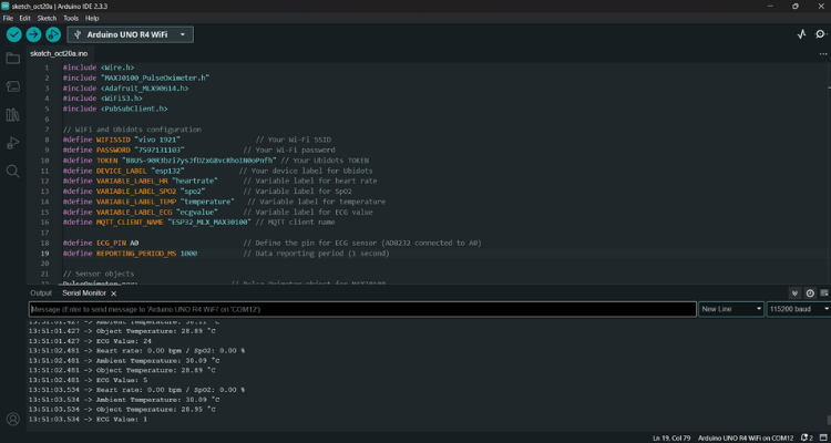
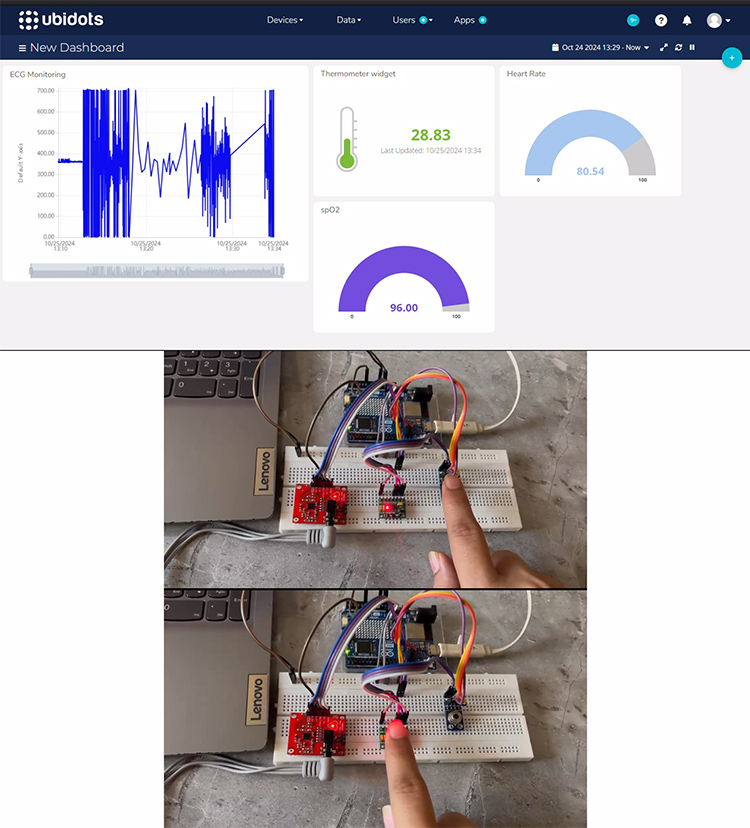
So, that’s it about the working of this project.
Complete Project Code
#include <Wire.h>
#include "MAX30100_PulseOximeter.h"
#include <Adafruit_MLX90614.h>
#include <WiFiS3.h>
#include <PubSubClient.h>
// WiFi and Ubidots configuration
#define WIFISSID "Wi-Fi SSID"                  // Your Wi-Fi SSID
#define PASSWORD " Wi-Fi password"              // Your Wi-Fi password
#define TOKEN " Ubidots TOKEN" // Your Ubidots TOKEN
#define DEVICE_LABEL "esp132"             // Your device label for Ubidots
#define VARIABLE_LABEL_HR "heartrate"      // Variable label for heart rate
#define VARIABLE_LABEL_SPO2 "spo2"         // Variable label for SpO2
#define VARIABLE_LABEL_TEMP "temperature"   // Variable label for temperature
#define VARIABLE_LABEL_ECG "ecgvalue"      // Variable label for ECG value
#define MQTT_CLIENT_NAME "ESP32_MLX_MAX30100" // MQTT client name
#define ECG_PIN A0                         // Define the pin for ECG sensor (AD8232 connected to A0)
#define REPORTING_PERIOD_MS 1000           // Data reporting period (1 second)
// Sensor objects
PulseOximeter pox;                      // Pulse Oximeter object for MAX30100
Adafruit_MLX90614 mlx = Adafruit_MLX90614(); // MLX90614 temperature sensor
uint32_t tsLastReport = 0;              // Time for the last data report
// WiFi and MQTT clients
WiFiClient espClient;
PubSubClient client(espClient);
// Buffers for MQTT topic and payload
char topic[150];
char payload[700];
// Function to connect to Wi-Fi
void setup_wifi() {
   delay(10);
   Serial.println();
   Serial.print("Connecting to ");
   Serial.println(WIFISSID);
   WiFi.begin(WIFISSID, PASSWORD);
   while (WiFi.status() != WL_CONNECTED) {
       delay(1000);
       Serial.print(".");
   }
   Serial.println();
   Serial.println("WiFi connected");
   Serial.println("IP address: ");
   Serial.println(WiFi.localIP());
}
// Function to reconnect to MQTT broker
void reconnect() {
   while (!client.connected()) {
       Serial.print("Attempting MQTT connection...");
       if (client.connect(MQTT_CLIENT_NAME, TOKEN, "")) {
           Serial.println("connected");
       } else {
           Serial.print("failed, rc=");
           Serial.print(client.state());
           Serial.println(" try again in 2 seconds");
           delay(2000);
       }
   }
}
// Callback routine executed when a pulse is detected
void onBeatDetected() {
   Serial.println("Beat Detected!");
}
void setup() {
   Serial.begin(115200);  // Begin Serial communication
   setup_wifi();           // Connect to Wi-Fi
   client.setServer("industrial.api.ubidots.com", 1883);
   // Initialize the MAX30100 Pulse Oximeter
   Serial.print("Initializing MAX30100 Pulse Oximeter...");
   if (!pox.begin()) {
       Serial.println("FAILED");
       for (;;);  // Stuck here if initialization fails
   } else {
       Serial.println("SUCCESS");
   }
   // Set the IR LED current for the MAX30100
   pox.setIRLedCurrent(MAX30100_LED_CURR_7_6MA);
   pox.setOnBeatDetectedCallback(onBeatDetected);
   // Initialize the MLX90614 temperature sensor
   Serial.print("Initializing MLX90614 Temperature Sensor...");
   if (!mlx.begin()) {
       Serial.println("FAILED");
       for (;;);  // Stuck here if initialization fails
   } else {
       Serial.println("SUCCESS");
   }
   // Initialize ECG pin as input
   pinMode(ECG_PIN, INPUT);
   Serial.println("ECG Sensor Initialized...");
}
void loop() {
   if (!client.connected()) {
       reconnect();
   }
   // Update the MAX30100 sensor readings
   pox.update();
   // Read ECG analog signal from the AD8232
   int ecgValue = analogRead(ECG_PIN);
   // Send data to Ubidots every REPORTING_PERIOD_MS
   if (millis() - tsLastReport > REPORTING_PERIOD_MS) {
       // Get heart rate and SpO2
       float heartRate = pox.getHeartRate();
       float spo2 = pox.getSpO2();
       // Read the ambient and object temperature from MLX90614
       float ambientTemp = mlx.readAmbientTempC();
       float objectTemp = mlx.readObjectTempC();
       // Print values to Serial Monitor
       Serial.print("Heart rate: ");
       Serial.print(heartRate);
       Serial.print(" bpm / SpO2: ");
       Serial.print(spo2);
       Serial.println(" %");
       Serial.print("Ambient Temperature: ");
       Serial.print(ambientTemp);
       Serial.println(" °C");
       Serial.print("Object Temperature: ");
       Serial.print(objectTemp);
       Serial.println(" °C");
       Serial.print("ECG Value: ");
       Serial.println(ecgValue);
       // Create topic and payload
       sprintf(topic, "/v1.6/devices/%s", DEVICE_LABEL);
       sprintf(payload, "{"%s": {"value": %.2f}, "%s": {"value": %.2f}, "%s": {"value": %.2f}, "%s": {"value": %d}}",
               VARIABLE_LABEL_HR, heartRate, VARIABLE_LABEL_SPO2, spo2, VARIABLE_LABEL_TEMP, objectTemp, VARIABLE_LABEL_ECG, ecgValue);
       // Publish data to Ubidots
       client.publish(topic, payload);
       client.loop();  // Handle MQTT client
       // Update last report time
       tsLastReport = millis();
   }
}


