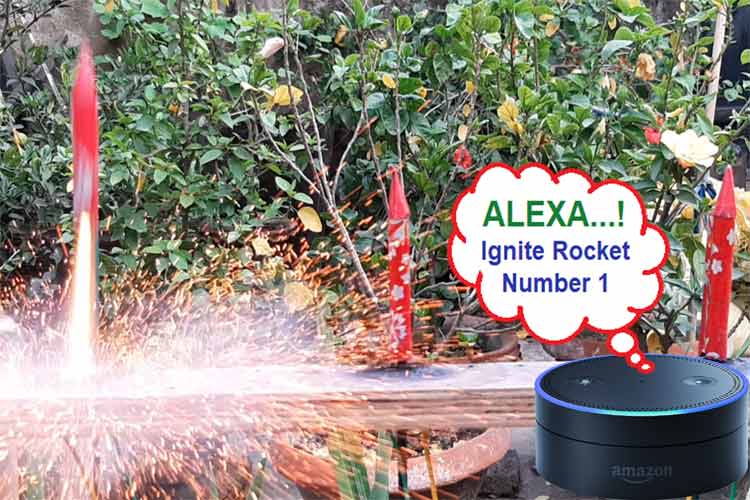
As the winter season approaches; comes that time of the year when the festival of lights is celebrated. Yes, we are talking about Diwali which is a true Indian festival celebrated across the globe. This year, Diwali is already over, and seeing people firecrackers, I came up with the idea of building the Alexa based Voice Controlled Rocket Launcher or Igniter, which can launch rockets with just voice command, making it very safe and fun for children.
To make it clear, I am not here for encouraging people to fire crackers on Diwali, the Indian government has enforced restrictions on crackers to curb pollution and it is our responsibility to adhere to it. The idea here is that instead of spending the whole day firing crackers, let's build a cool voice-controlled Arduino rocket igniter and fire a few rockets in style. I see that as a win-win.
This Arduino rocket launcher will be very different from others. It has a very sturdy chassis made out of plywood, a reliable relay-based control mechanism, and a very unique mechanism for launching and reloading the rockets, so without further delay, let's get right into the building process.
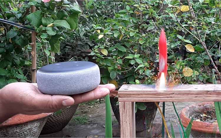
Alexa based Voice Controlled Rocket Launcher - Working
The working mechanism of the circuit is very simple, the main component which is responsible for launching the rocket is the nichrome wire, and it comes in the form of a heating coil. This nichrome wire will act as the rocket igniter. How? I will show you later.
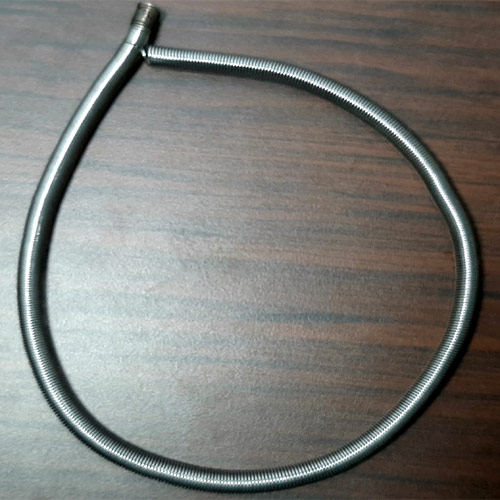
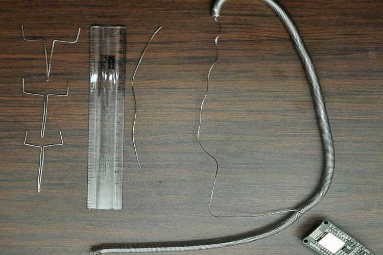
As you can see in the image above, the nichrome wire comes in the form of a heater coil, for me, it was the easiest way to get it. We have to pull it straight and bend it to form a shape that looks like as shown in the image below.
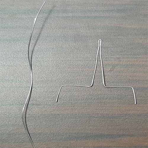
Once we have done this, we will power it with a 12V lead-acid battery and it will glow red hot. This will be enough to ignite the black powder inside the rocket and it will work just like a normal fuse dose. Be advised that this is a high power rocket launch controller, the current required to make the wire red hot is high. Follow safety advice when working with high currents.
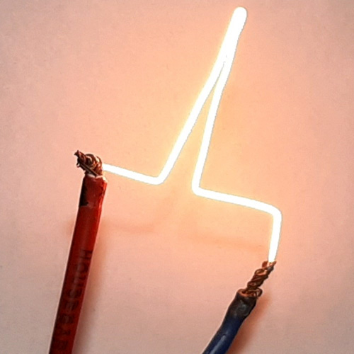
Once the testing is done, the only thing remaining is the controlling process, which we will be doing as we proceed further in the article.
Launchpad for our NodeMCU Rocket Launch Controller
For this build, let's make a launchpad. With the launchpad done, we can easily reload some crackers and launch them very easily. I have built a launchpad that looks like the one shown in the image shown below.
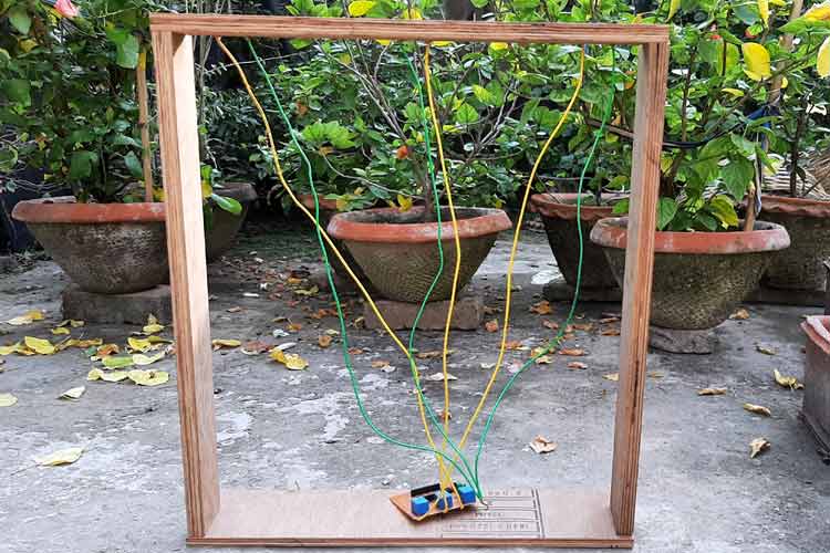
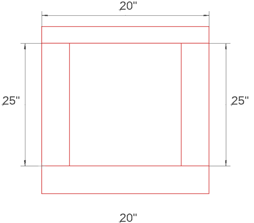
Let's go through the step by step process of building the launchpad. For the two sides of the frame, I have used two (25X3X1.5) inch long pieces of plywood. For the top part, I have used a (20X3X1.5) inch long part of plywood and for the base, I have used a (20X6X1.5) inch long piece of plywood, which will give it a little more stability. The image below will give you a clear idea.
Now, it's time to make the nichrome wire-based filaments, which will act as a fuse for our rocket. For that, I have bought a 1000W nichrome wire base heating coil, straightened it up, and made the structure which is shown below. I had to use two pliers and side cutters to shape the nichrome wire as shown below.
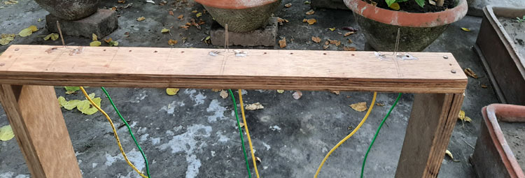
Once this was done, I divided the 20” piece of plywood block into seven pieces measured it, and drilled holes to put the nichrome wire-based filaments in, and once it was done, it looked like the images below.
But before placing the filaments, I have attached 1 sq mm thick copper wire in each terminal and passed them through the holes, once everything was done, it looked like the image below.
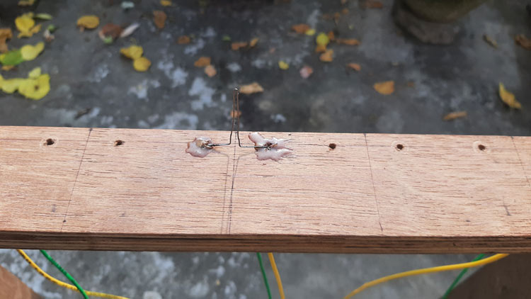
As you can see, I have also put in the two-component adhesive to secure the wire and filaments in place. With that done, our launchpad is complete. And as you can see from the first picture in this section, I have directly attached the filament wires to the PCB because we are dealing with very high currents so I did not bother to place a screw terminal, and that marks the end of our chassis building process.
Components Required for Alexa Controlled Rocket Launcher
For the hardware side of things, we have used very generic parts which you can get pretty easily from your local hobby store, a complete list of items is given below.
- 12V-Relay - 3
- BD139 Transistor - 3
- 1N4004 Diode - 3
- 5.08 mm Screw Terminal - 1
- LM7805 - Voltage Regulator - 1
- 100uF Decoupling Capacitor - 2
- 5.1V Zener Diode - 1
- NodeMCU (ESP8266-12E) Board - 1
- Dotted Perf Board - ½
- Connecting Wire - 10
Arduino Rocket Launcher Circuit Diagram
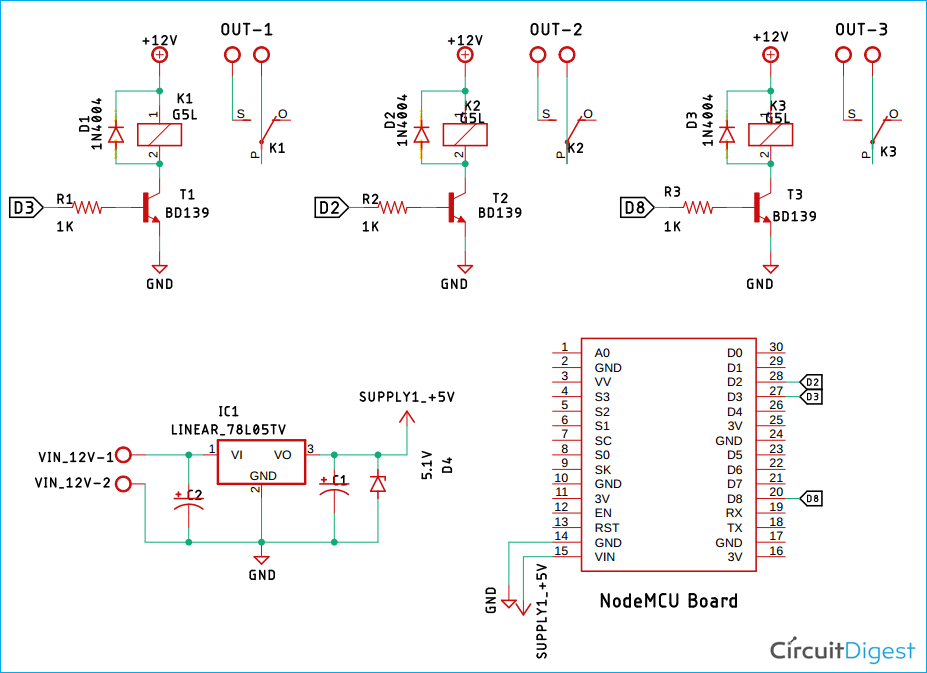
The complete schematic for Alexa Controlled Rocket Launcher is given below. I have used tags to connect one pin to another. If you look close enough, it should not be difficult to interpret the schematic.
The Circuit Construction is pretty straightforward, So I will not go into the details very much.
First, we have IC1 which is an LM7805 voltage regulator, with its 100uF decoupling capacitors denoted by C1 and C2. After that, we have the heart of our project, the NodeMCU board, which houses the ESP-12E module. Since we are using a 12V lead-acid battery to power the whole circuit, which is why we have to use the LM7805 to first convert it to 12V to 5V to power the NodeMCU board. We are doing so because the onboard AMS1117 voltage regulator is not sufficient enough to convert 12V directly to 3.3V, which is why 7805 is necessary.
Moving on, we have three 12V relays, for this demonstration, we are using three relays, but as we have previously mentioned, the launchpad has a placeholder for 7 rockets. You can tweak the code a little bit and place all seven rockets to launch altogether. The three relays are driven by a T1, T2, and T3 which are three NPN transistors, and they are sufficient enough to drive the load of a real. Finally, we have three freewheeling diodes that are protecting the circuit from high voltage spikes generated by the relay.
Building the Circuit on PerfBoard
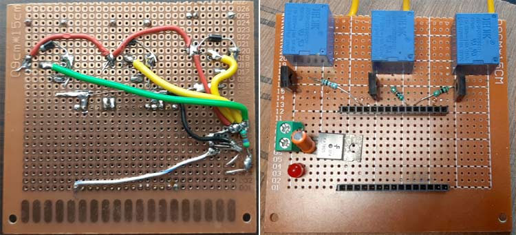
As you can see from the main image, the idea was to make a simple circuit that can handle a huge amount of current for a short period, as per our testing, 800 milliseconds is enough to light up a piece of paper. So, we build the circuit on a piece of perfboard and connect all major connections with 1 sq mm thick copper wire. After we finished soldering the board. Once we were finished, it looked like something that is shown below.
Programming NodeMCU for Alexa Controlled Rocket Launcher
Now that the hardware is ready, it's time to start coding for our Alexa based voice controlled rocket launcher. The complete code can be found at the end of this page, but before we start, it is important to add the required libraries to your Arduino IDE. Make sure you add the right libraries from the link given below else the code will throw errors when compiled.
After adding the required libraries, you can directly upload the code given at the bottom of this page to check if the circuit is working. If you want to know how the code works, then keep reading.
Like always, we begin the program by adding the required header files and defining the pin names and credentials for our hotspot.
#include <ESP8266WiFi.h>
#include <Espalexa.h>
//define the GPIO connected with Relays
#define ROCKET_1_PIN 4
#define ROCKET_2_PIN 13
#define ROCKET_3_PIN 15
// WiFi Credentials
const char* ssid = "deba_2.4";
const char* password = "il2ww*ee";
Moving on with our code, we have our function prototypes and callback function definitions.
Function connectToWiFi() is used to connect to the Wi-Fi network and this function returns true when Wi-Fi gets successfully connected.
Next, we have our callback functions, this functions will be called when we give a command to Alexa, the espalexa API handles these functions
void allrockets(uint8_t brightness);
void firstrocket(uint8_t brightness);
void secondrocket(uint8_t brightness);
void thirdrocket(uint8_t brightness);
Next, we define the Device Names. These defined device names will be reflected on the Alexa app and when we say a command, Alexa will recognize the devices by these names. So these names are very important.
// Device names
String First_Device_Name = "All Rockets";
String Secound_Device_Name = "Rocket One";
String Third_Device_Name = "Rocket Two";
String Forth_Device_Name = "Rocket Three";
Next, we define a boolean variable wifiStatus, which will hold the connection status of the Wi-Fi. Finally, we create an Espalexa object espalexa. We will be using this object to configure the NodeMCU.
// wifi status check
boolean wifiStatus = false;
// Espalexa Object
Espalexa espalexa;
Next, we have our void setup() section. In this section, we initialize serial communication for debugging with Serial.begin() function. We set all the previous defined pins as output with pinMode() function, next we call the connectToWiFi() function, it will try to connect to Wi-Fi for fifteen times if it is connected, it will return true if it doesn't get connected, it will return false and the code will execute a while() loop forever. If the Wi-Fi connection is successful, we add the previously defined devices to the Alexa object by using the espalexa.addDevice() function.This function takes two arguments, first is the Device Name, second is the name of the callback function, when we put out a command to Alexa, the adjacent function will be called. Once we are done doing it for all four of our devices, we call the begin() methods for the espalexa object.
void setup(){
  Serial.begin(115200); // Enable Serial for debugging messages
  pinMode(ROCKET_1_PIN, OUTPUT);  //setup ESP pins as output
  pinMode(ROCKET_2_PIN, OUTPUT);  //setup ESP pins as output
  pinMode(ROCKET_3_PIN, OUTPUT);  //setup ESP pins as output
  wifiStatus = connectToWiFi(); // Connect to local Wi-Fi Network
    if (wifiStatus)  {// setup all espalexa devices
    // Define your devices here.
    espalexa.addDevice(First_Device_Name, allrockets); //simplest definition, default state off
    espalexa.addDevice(Secound_Device_Name, firstrocket);
    espalexa.addDevice(Third_Device_Name, secondrocket);
    espalexa.addDevice(Forth_Device_Name, thirdrocket);
    espalexa.begin();
  }
  else  {
    while (1)  {
      Serial. println("Cannot connect to WiFi. Please check data and reset the ESP.");
      delay(2500);
    }
  }
}
In the loop section, we call the loop() method of the espalexa object that will always check for any incoming command and call the callback function if it finds it true.
void loop(){
  espalexa.loop();
  delay(1);
}
Next, we define all our callback functions, in this section, we will define what happens when this callback function is called. When the allrockets() function is called, all the rockets are going to be launched together. For that, we are going to turn on the relay for 00 ms and after that, we are going to turn off the relays. In my tests, I have found that for the specified length of nichrome wire, I need 800ms of delay to completely heat the wire, this may or may not be the case for you. So choose the delay accordingly.
void allrockets(uint8_t brightness)
{
  if (brightness == 255)
  {
    digitalWrite(ROCKET_1_PIN, HIGH);
    digitalWrite(ROCKET_2_PIN, HIGH);
    digitalWrite(ROCKET_3_PIN, HIGH);
    delay(800);
    digitalWrite(ROCKET_1_PIN, LOW);
    digitalWrite(ROCKET_2_PIN, LOW);
    digitalWrite(ROCKET_3_PIN, LOW);
    Serial.println("All Rockets Launched");
  }
}
Next, we have our first rocket(), this gets called when we call Alexa and say tie command to launch the first rocket. The process is very similar, we turn on the relay for 800ms and turn off.
void firstrocket(uint8_t brightness){
   if (brightness == 255)
  {
    digitalWrite(ROCKET_1_PIN, HIGH);
    delay(800);
    digitalWrite(ROCKET_1_PIN, LOW);
    Serial.println("First Rocket Launched");
  }
}
Finally, we have our connectToWiFi() function. This function is pretty generic and self-explanatory, so I will not go into the details about this function. This function connects the ESP to Wi-Fi and returns the connection status.
boolean connectToWiFi()
{
  boolean state = true;
  int i = 0;
  WiFi.mode(WIFI_STA);
  WiFi.begin(ssid, password);
  Serial.println("");
  Serial.println("Connecting to WiFi");
  // Wait for connection
  Serial.print("Connecting...");
  while (WiFi.status() != WL_CONNECTED) {
    delay(500);
    Serial.print(".");
    if (i > 15) {
      state = false; break;
    }
    i++;
  }
  Serial.println("");
  if (state) {
    Serial.print("Connected to ");
    Serial.println(ssid);
    Serial.print("IP address: ");
    Serial.println(WiFi.localIP());
  }
  else {
    Serial.println("Connection failed.");
  }
  return state;
}
This function defined marks the end of the coding part.
Configuring Alexa with Alexa Android Application
Alexa will only accept commands if and only if it recognizes the esp8866 device. For that, we need to configure Alexa with the help of the Alexa app on Android. One important thing to do before we proceed any further is that we need to make sure that Alexa is configured with our android application.
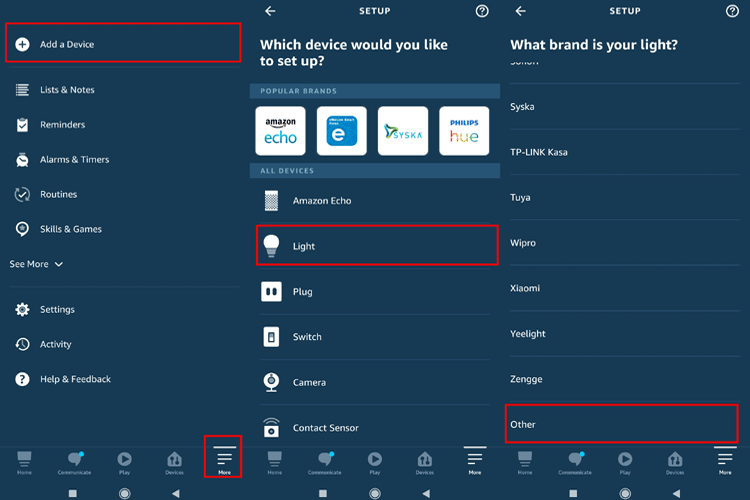
To do that, go to the more section of the Alexa app and click on the Add a Device option, click on Light, then scroll down at the bottom of the page and click on Other.
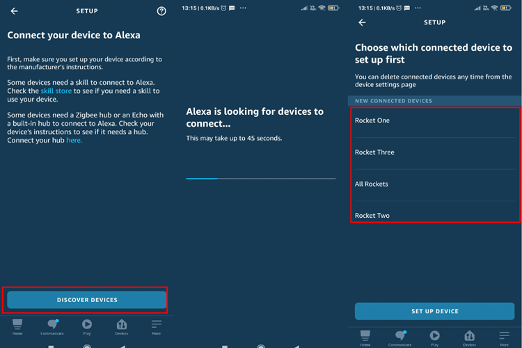
Next, click on DISCOVER DEVICE and wait for a moment after that Alexa will find new devices. Once Alexa finds the devices, you need to click on them and add them to their respective places/categories, and you are done.
Alexa Controlled Rocket Launcher - Testing
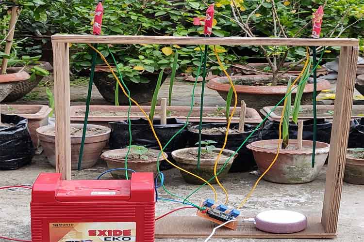
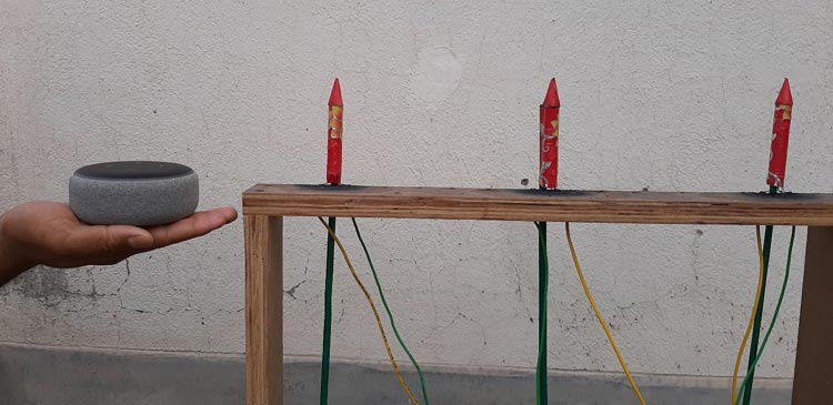
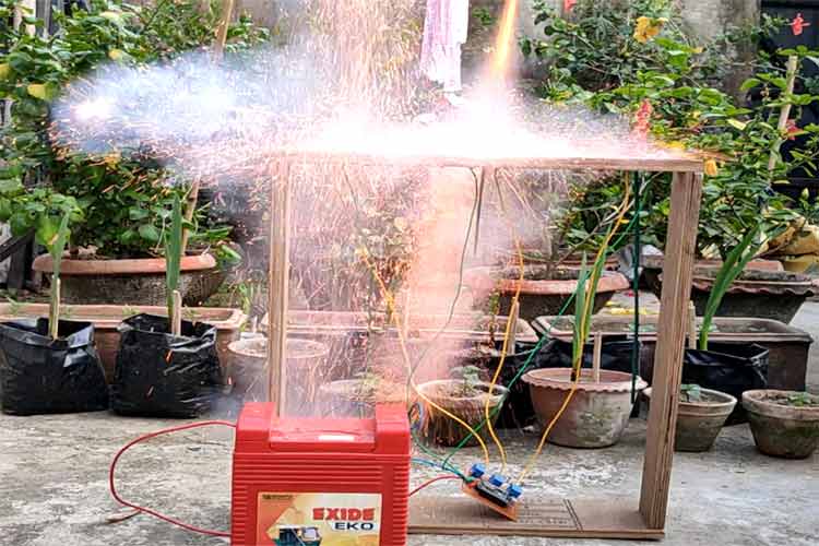
For the testing process, I went to my garden, pulled all the fuses from the rocket, placed them in their respective places, and I shouted Alexa…! Turn on all Rockets, with my fingers crossed. And all the rockets flew by marking my efforts as a huge success. It looked something like this.
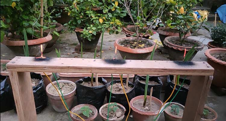
Finally, once more I said Alexa…! Turn on all rockets to get an epic picture of the filaments which you can see below.
For a more epic experience, I highly recommend you to watch the video.
Complete Project Code
/**********************************************************************************
    TITLE: Alexa control 3 channel Rocket Launcher Can be upgraded to 7 channels very easily
    by Debashis Das (Tech StudyCell)
    Download the Espalexa library:
    https://github.com/Aircoookie/Espalexa
 **********************************************************************************/
#include <ESP8266WiFi.h>
#include <Espalexa.h>
//define the GPIO connected with Relays
#define ROCKET_1_PIN 4
#define ROCKET_2_PIN 13
#define ROCKET_3_PIN 15
// WiFi Credentials
const char* ssid = "deba_2.4";
const char* password = "il2ww*ee";
// prototypes
boolean connectToWiFi();
//callback functions
void allrockets(uint8_t brightness);
void firstrocket(uint8_t brightness);
void secondrocket(uint8_t brightness);
void thirdrocket(uint8_t brightness);
// Device names
String First_Device_Name = "All Rockets";
String Secound_Device_Name = "Rocket One";
String Third_Device_Name = "Rocket Two";
String Forth_Device_Name = "Rocket Three";
// wifi status check
boolean wifiStatus = false;
// Espalexa Object
Espalexa espalexa;
void setup()
{
  // Enable Serial for debugging messages
  Serial.begin(115200);
  //setup ESP pins as output
  pinMode(ROCKET_1_PIN, OUTPUT);
  pinMode(ROCKET_2_PIN, OUTPUT);
  pinMode(ROCKET_3_PIN, OUTPUT);
  // Connect to local Wi-Fi Network
  wifiStatus = connectToWiFi();
  // If Wi-Fi is connected setup all espalexa devices
  if (wifiStatus)
  {
    // Define your devices here.
    espalexa.addDevice(First_Device_Name, allrockets); //simplest definition, default state off
    espalexa.addDevice(Secound_Device_Name, firstrocket);
    espalexa.addDevice(Third_Device_Name, secondrocket);
    espalexa.addDevice(Forth_Device_Name, thirdrocket);
    espalexa.begin();
  }
  else
  {
    while (1)
    {
      Serial.println("Cannot connect to WiFi. Please check data and reset the ESP.");
      delay(2500);
    }
  }
}
void loop()
{
  espalexa.loop();
  delay(1);
}
//callback functions
void allrockets(uint8_t brightness)
{
  if (brightness == 255)
  {
    digitalWrite(ROCKET_1_PIN, HIGH);
    digitalWrite(ROCKET_2_PIN, HIGH);
    digitalWrite(ROCKET_3_PIN, HIGH);
    delay(800);
    digitalWrite(ROCKET_1_PIN, LOW);
    digitalWrite(ROCKET_2_PIN, LOW);
    digitalWrite(ROCKET_3_PIN, LOW);
    Serial.println("All Rockets Launched");
  }
}
void firstrocket(uint8_t brightness)
{
  if (brightness == 255)
  {
    digitalWrite(ROCKET_1_PIN, HIGH);
    delay(800);
    digitalWrite(ROCKET_1_PIN, LOW);
    Serial.println("First Rocket Launched");
  }
}
void secondrocket(uint8_t brightness)
{
  if (brightness == 255)
  {
    digitalWrite(ROCKET_2_PIN, HIGH);
    delay(800);
    digitalWrite(ROCKET_2_PIN, LOW);
    Serial.println("Secound Rocket Launched");
  }
}
void thirdrocket(uint8_t brightness)
{
  if (brightness == 255)
  {
    digitalWrite(ROCKET_3_PIN, HIGH);
    delay(800);
    digitalWrite(ROCKET_3_PIN, LOW);
    Serial.println("Third Rocket Launched");
  }
}
// connect local Wi-Fi – Returns true if successful or false if not
boolean connectToWiFi()
{
  boolean state = true;
  int i = 0;
  WiFi.mode(WIFI_STA);
  WiFi.begin(ssid, password);
  Serial.println("");
  Serial.println("Connecting to WiFi");
  // Wait for connection
  Serial.print("Connecting...");
  while (WiFi.status() != WL_CONNECTED) {
    delay(500);
    Serial.print(".");
    if (i > 20) {
      state = false; break;
    }
    i++;
  }
  Serial.println("");
  if (state) {
    Serial.print("Connected to ");
    Serial.println(ssid);
    Serial.print("IP address: ");
    Serial.println(WiFi.localIP());
  }
  else {
    Serial.println("Connection failed.");
  }
  return state;
}
