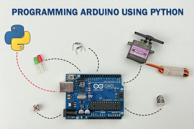
Today, we are goin to learn how we can program our Arduino boards using Python. Long back, we wrote a short Arduino Python tutorial to demonstrate how we can control an LED from python code. But it was using serial monitor and there was limitation with what you could do with it. But today we will show you how you can turn your Arduino board into a data acquisition tool that integrates seamlessly with your Python code, regardless of the operating system. In fact, you can gain control over the IOs of the Arduino board using Python. This literally lets your enjoy all the functionalities on a Arduino board using python code.
It’s a cool idea, right?. So, without further delay, let’s explore this concept in more detail.
Can I Code Arduino using Python?
As we already know, interacting with an Arduino board using Python is possible, but it requires a specific approach. This involves real-time programming, where our Python program communicates with the Arduino board. To achieve this, we need a wired or wireless connection between the Arduino board and the device running the Python program. This is where Firmata comes in.
What is Firmata?
Firmata is a communication protocol used to connect microcontrollers, such as Arduino, with a computer. It allows you to control and interact with the microcontroller’s inputs and outputs directly from the software on your PC. Firmata is built on the MIDI message format, which can handle messages of varying lengths. However, this isn't an issue for Firmata and microcontrollers, as the amount of data transferred is usually minimal.
The key advantage of Firmata is that it has been implemented in multiple programming languages, including Python. This means you can use Firmata with different languages to communicate with your microcontroller, making it versatile and easy to integrate into various software environments. Here in this article, we will be focusing on Python.
So, let us know how it works!
How does Firmata work?
It’s really simple as the base architecture to implement Firmata already exists with the default Arduino IDE installation. Below you can see the steps to follow,
Installing the standard Firmata program on the Arduino board - thereby the Arduino board awaits the Firmata protocol via USB.
Including the PyFirmata library in your existing Python code - so, after including PyFirmata, we can start adding PyFirmata-dedicated functions to communicate with Arduino.
Completing the hardware setup - preparing the hardware with all the necessary circuit connections to ensure proper communication between the sensors, actuators, and PC while keeping the Arduino board in the middle.
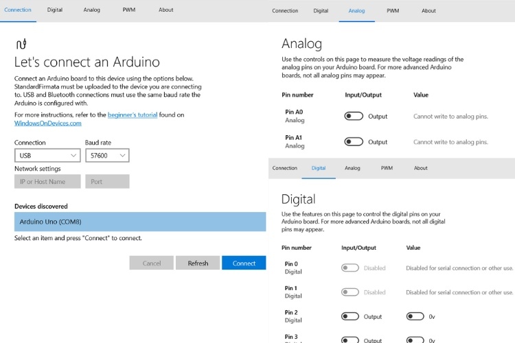
In case you’d like to experience Firmata without writing a single line of code, there is software available for Windows users that can be used to explore the Firmata protocol with a simple, user-friendly UI.
The above image shows the user interface of Windows Remote Arduino Experience Software that you can download from the Microsoft store.
Components Required for Experimenting with Firmata and Arduino
As we are going to do some basic I/O practice, the components are going to be more straightforward.
Aruino UNO R3 Board x1
LED 5mm x1
Push Button x1
10K Potentiometer x1
SG90 Micro Servo Motor x1
Breadboard x1
Arduino Programming USB Cable x1
Resistor 330Ω, 10KΩ - each one nos
Connecting wires - Required Quantity
Arduino & Pyfirmata Prerequisite
First, let's prepare the Arduino board to communicate using the Firmata protocol.
Programming Arduino UNO Board:
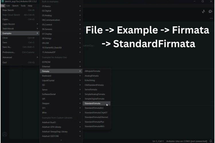
As I mentioned earlier, there is no need to write a single line of code on the Arduino side. There is a pre-built example for the Firmata protocol available in the Arduino IDE. In fact, there are several modes of connectivity available, like Bluetooth, WiFi, and more. I'll leave the rest for you to explore. So, enough talk—let's start programming now!
Above, you can see the image showing the Firmata library location. You can follow this location to open the standard Firmata program. Now, after selecting the appropriate port and board type, upload the program. That's it.
After a successful upload, things are done on the Arduino side. Next, we are going to play with Python.
Installing PyFirmata:
As per our testing, we found that this PyFirmata module didn't work with Python 3.11 or 3.12. So, the recommended versions are 3.6 to 3.10. Follow the steps below for a smooth installation.
Installing a supported version of Python: In my case, I installed Python 3.10.
Installing your preferred IDE: Using the direct Python IDLE should also work, but as a beginner, I recommend using PyCharm Community Edition.
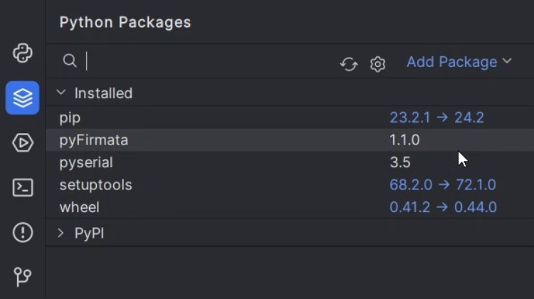
Installing required packages: The only required package here is PyFirmata, and while installing PyFirmata, PySerial is also installed automatically.
Above, you can see the list of packages installed using the Package Manager in PyCharm.
Thereby, the installation of the required software is completed. Next, we can go on to programming the Arduino using Python.
Basic IO Functions of Pyfirmata
There are five basic I/O operations that we can perform using PyFirmata:
Digital Read
Digital Write
Analog Read
Analog Write or PWM Control
Servo Motor Control
Let's see all these in detail.
Digital Read:
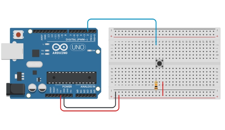
Here, to perform the Digital Read using python on Arduino, I am going to connect a push button to pin 2 of the Arduino. This pin 2 is then pulled down using a 10k resistor to maintain a stable low state.
The above image shows the circuit diagram clearly. Once you complete the circuit diagram, connect the Arduino board to the computer using the USB cable. Next is the coding part.
Python Code for Digital Read on Arduino
Let's break down the code.
Step 1:
from pyfirmata import Arduino, util
This line imports specific parts of the PyFirmata library, namely Arduino (to connect to the Arduino board) and util (which contains helpful tools like the Iterator).
Step 2:
board = Arduino('COM8')
This line establishes a connection between your computer and the Arduino board. 'COM8' is the port where the Arduino is connected. (On different computers, this might be a different port like COM3, COM4, etc., or /dev/ttyACM0 on Linux.)
Step 3:
button_pin = board.get_pin('d:2:i')This line sets up pin 2 on the Arduino as an input pin. Here's what the parameters mean:
'd' stands for "digital" (as opposed to analog).
'2' is the pin number on the Arduino.
'i' stands for "input," meaning this pin will receive signals (like the button being pressed).
Step 4:
it = util.Iterator(board)
it.start()
it = util.Iterator(board): creates an Iterator object that will keep checking the state of the pins on the Arduino.
it.start(): starts the Iterator. Without it, the script wouldn't be able to continuously read the state of the button.
Step 5:
button_state = button_pin.read()
“button_pin.read()” reads the state of the button and stores in “button_state”. The state can be:
True (if the button is pressed),
False (if the button is not pressed),
None (if the state is unknown or if the pin hasn’t been initialized yet).
Step 6:
board.exit()
This safely closes the connection to the Arduino, ensuring that all resources are freed and the Arduino is ready for the next use.
Code to control Arduino GPIO pins using Python Firmata
from pyfirmata import Arduino, util
import time

# Replace 'COM8' with your Arduino port
board = Arduino('COM8')  # Establish a connection to the Arduino board

# Set up digital pin 2 as an input pin for the button
button_pin = board.get_pin('d:2:i')  # 'd' stands for digital, '2' is the pin number, 'i' is for input

# Start the iterator to continuously read and update pin states
it = util.Iterator(board)
it.start()

try:
   while True:
       button_state = button_pin.read()  # Read the state of the button (True, False, or None)
       print(f"Button state: {button_state}")  # Print the current button state to the console
       time.sleep(1)  # Wait for 1 second before reading the button state again

except KeyboardInterrupt:
   print("Program interrupted by user.")  # Print a message if the program is interrupted

finally:
   board.exit()  # Safely exit and close the connection to the Arduino
If you run this Python script, the output you get will look like below GIF Video.
Digital Write:
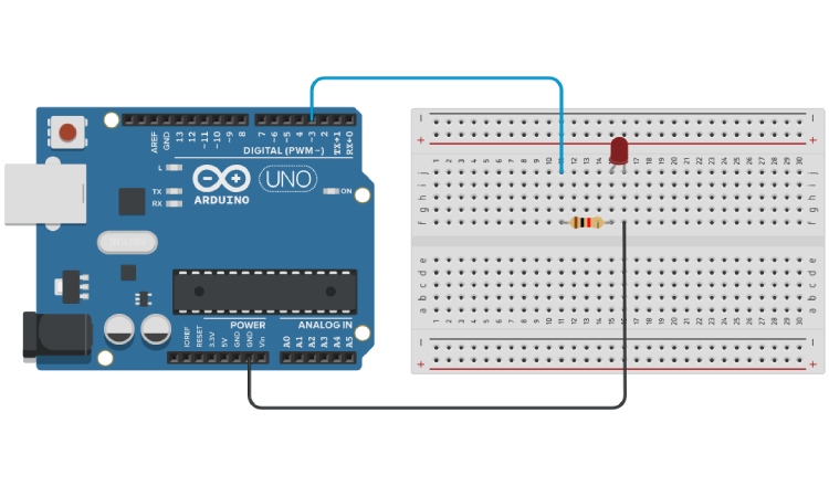
We will be using a simple LED to demonstrate how we can do digital write on python for Arduino . We will connect an LED to pin 3 of the Arduino. The pin 3 is used as an output pin to control the LED. The LED is connected in series with a current-limiting resistor to prevent excessive current from damaging the LED.
The above image shows the circuit diagram clearly. After completing the circuit, connect the Arduino board to your computer using a USB cable. Now, let's move on to the coding part.
Python Code for Arduino Digital Write:
Let's break down the code while skipping the similar parts.
1. Setting up the LED
led_pin = board.get_pin('d:3:o')led_pin = board.get_pin('d:3:o'): Sets up pin 3 on the Arduino as an output pin. The parameters mean:
'd' stands for "digital" (as opposed to analog).
'3' is the pin number on the Arduino.
'o' stands for "output," meaning this pin will send signals (like turning the LED on or off).
2. Main Loop
while True:
   led_pin.write(1)  # Turn LED on
   time.sleep(1)     # Wait for 1 second
   led_pin.write(0)  # Turn LED off
   time.sleep(1)     # Wait for 1 second
while True: Creates an infinite loop, making the LED blink repeatedly.
led_pin.write(1): Turns the LED on by sending a signal to pin 3.
time.sleep(1): Pauses the program for 1 second before the next action.
led_pin.write(0): Turns the LED off.
time.sleep(1): Pauses the program for another 1 second, completing the blink cycle.
The Full Code:
from pyfirmata import Arduino, util
import time

# Replace 'COM8' with your Arduino port
board = Arduino('COM8')

# Set up digital pin 3 as an output pin for the LED
led_pin = board.get_pin('d:3:o')

# Start the iterator to continuously read and update pin states
it = util.Iterator(board)
it.start()

try:
   while True:
       led_pin.write(1)  # Turn LED on
       time.sleep(1)     # Wait for 1 second
       led_pin.write(0)  # Turn LED off
       time.sleep(1)     # Wait for 1 second

except KeyboardInterrupt:
   print("Program interrupted by user.")  # Print a message when interrupted

finally:
   board.exit()  # Safely exit and close the connection to the Arduino
If you run this Python script, the output will be an LED that blinks on and off every second.
Analog Read:
Circuit Diagram:
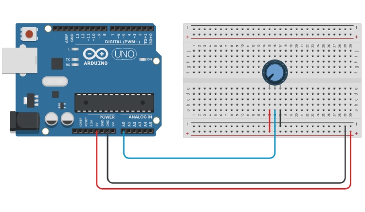
For reading analog sensor on arduino using python, we'll connect an analog sensor (such as a potentiometer or temperature sensor) to the Arduino on analog pin A0. The sensor will output a variable voltage that the Arduino will read and process as an analog input.
The circuit diagram above provides a clear illustration of how to connect your sensor to the Arduino. After wiring the circuit, connect the Arduino board to your computer using a USB cable. Now, let's move on to the coding aspect.
Code Explanation:
Let's break down the key parts of the code.
1. Setting Up the Sensor:
sensor_pin = board.get_pin('a:0:i')Configures analog pin A0 on the Arduino as an input pin.
'a' stands for "analog."
'0' is the analog pin number.
'i' stands for "input," indicating that this pin will receive signals from the sensor.
2. Main Loop:
while True:
   # Read the current sensor value from analog pin A0
   sensor_value = sensor_pin.read()

   # Print the sensor value to the console
   print(f"Sensor value: {sensor_value}")

   # Wait for 1 second before the next reading
   time.sleep(1)
sensor_pin.read(): Reads the current value from the analog sensor connected to pin A0. The value is typically between 0 (0V) and 1 (5V).
print(f"Sensor value: {sensor_value}"): Displays the sensor's current value in the console.
time.sleep(1): Pauses the program for 1 second before the next reading, allowing you to see each value distinctly.
Python Code to read Analog Sensor on Arduino
from pyfirmata import Arduino, util
import time

# Establish connection to the Arduino board (replace 'COM8' with your specific port)
board = Arduino('COM8')

# Set up the sensor on analog pin A0 as an input
sensor_pin = board.get_pin('a:0:i')

# Start an iterator to continuously update the pin values from the Arduino
it = util.Iterator(board)
it.start()

try:
   while True:
       # Read the current sensor value from analog pin A0
       sensor_value = sensor_pin.read()

       # Print the sensor value to the console
       print(f"Sensor value: {sensor_value}")

       # Wait for 1 second before the next reading
       time.sleep(1)

except KeyboardInterrupt:
   # Handle the program interruption by the user (Ctrl+C)
   print("Program interrupted by user.")

finally:
   # Safely exit the program and close the connection to the Arduino
   board.exit()
When you run this Python script, it will continuously read and display the sensor value every second.
Analog Write or PWM Control:
Circuit Diagram:
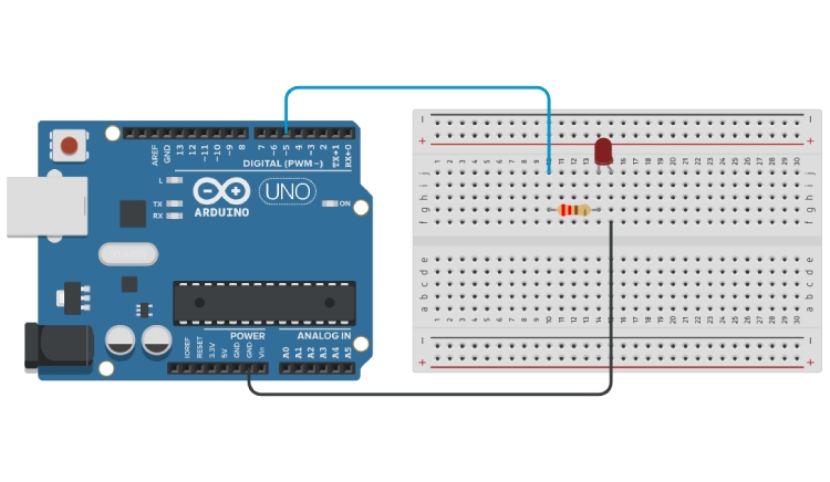
In this example, we will control the brightness of an LED using Pulse Width Modulation (PWM) in python on Arduino. The LED is connected to digital pin 5 of the Arduino, which is capable of PWM output. PWM allows us to vary the intensity of the LED by adjusting the duty cycle of the signal.
The above image shows the correct circuit diagram. Once you have set up the circuit, connect the Arduino to your computer using a USB cable. Now, let's move on to the coding section.
Python Code to Control Brightness of LED:
We'll break down the essential parts of the code to understand how it works.
1. Setting Up the LED for PWM:
led_pin = board.get_pin('d:5:p') # Digital pin 5 as PWM outputConfigures pin 5 on the Arduino as a PWM output pin. Here’s what the parameters mean:
'd' stands for "digital."
'5' is the pin number on the Arduino.
'p' stands for "PWM," allowing the pin to output a signal with varying duty cycles.
2. Main Loop:
while True:
   # Gradually increase the LED brightness from 0 to 255
   for brightness in range(256):
       led_pin.write(brightness / 255.0)  # Set LED brightness (0 to 1.0 scale)
       # time.sleep(0.01)  # Small delay for a visible effect

   # Gradually decrease the LED brightness from 255 to 0
   for brightness in range(255, -1, -1):
       led_pin.write(brightness / 255.0)  # Set LED brightness (0 to 1.0 scale)
       # time.sleep(0.01)  # Small delay for a visible effect
for brightness in range (256): This loop gradually increases the brightness of the LED from 0 (off) to 255 (full brightness).
led_pin.write(brightness / 255.0): Sets the brightness of the LED. The write () method takes a value between 0 and 1.0, so we divide the brightness by 255.
time.sleep(0.01): (Commented out in this example) Pauses the program briefly to create a smooth fading effect. Uncomment to slow down the transition.
The second loop does the reverse, gradually dimming the LED from full brightness back to off.
Python code for PWM control on Arduino
from pyfirmata import Arduino, util
import time

# Establish connection to the Arduino board (replace 'COM8' with your specific port)
board = Arduino('COM8')

# Set up the LED on digital pin 5 as a PWM output
led_pin = board.get_pin('d:5:p')  # Digital pin 5 as PWM output

# Start an iterator to continuously update the pin values from the Arduino
it = util.Iterator(board)
it.start()

try:
   while True:
       # Gradually increase the LED brightness from 0 to 255
       for brightness in range(256):
           led_pin.write(brightness / 255.0)  # Set LED brightness (0 to 1.0 scale)
           # time.sleep(0.01)  # Small delay for a visible effect

       # Gradually decrease the LED brightness from 255 to 0
       for brightness in range(255, -1, -1):
           led_pin.write(brightness / 255.0)  # Set LED brightness (0 to 1.0 scale)
           # time.sleep(0.01)  # Small delay for a visible effect

except KeyboardInterrupt:
   # Handle the program interruption by the user (Ctrl+C)
   print("Program interrupted by user.")

finally:
   # Safely exit the program and close the connection to the Arduino
   board.exit()
When you run this script, the LED will gradually fade in and out, creating a smooth pulsing effect.
Servo Motor Control:
Circuit Diagram:
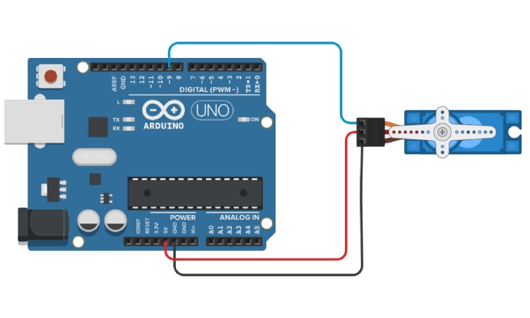
In this example, we'll control a servo motor using python an Arduino. The servo is connected to digital pin 9 of the Arduino. The servo motor can be rotated to a specified angle, typically between 0 and 180 degrees.
The circuit diagram above shows how to connect the servo motor to the Arduino. After wiring the circuit, connect the Arduino to your computer via a USB cable, and let's move on to the coding part.
Python Code Explanation for Controlling Arduino Servo Motor:
Here's a step-by-step breakdown of the code:
1. Setting Up the Servo:
# Set the pin where the servo is connected (e.g., pin 9)
servo_pin = board.get_pin('d:9:s')  # 'd' for digital, 9 is the pin number, 's' for servo
Configures pin 9 on the Arduino as a servo control pin.
'd' indicates that this is a digital pin.
'9' is the pin number.
's' stands for "servo," specifying that this pin will control a servo motor.
2. Sweeping the Servo:
while True:
   # Sweep from 0 to 180 degrees
   for angle in range(0, 181, 1):
       servo_pin.write(angle)  # Move servo to the specified angle
       time.sleep(0.001)  # Adjust the speed of the sweep

   # Sweep back from 180 to 0 degrees
   for angle in range(180, -1, -1):
       servo_pin.write(angle)  # Move servo to the specified angle
       time.sleep(0.001)
for angle in range(0, 181, 1): This loop rotates the servo from 0 to 180 degrees.
servo_pin.write(angle): Moves the servo to the specified angle.
time.sleep(0.001): Pauses the program briefly between angle changes to control the speed of the servo movement.
The second loop reverses the direction, sweeping the servo from 180 degrees back to 0.
Python Code for Servo Motor Control:
import time
from pyfirmata import Arduino

# Change the port to the one your Arduino is connected to
board = Arduino('COM8')

# Set the pin where the servo is connected (e.g., pin 9)
servo_pin = board.get_pin('d:9:s')  # 'd' for digital, 9 is the pin number, 's' for servo

def sweep_servo():
   try:
       while True:
           # Sweep from 0 to 180 degrees
           for angle in range(0, 181, 1):
               servo_pin.write(angle)  # Move servo to the specified angle
               time.sleep(0.001)  # Adjust the speed of the sweep

           # Sweep back from 180 to 0 degrees
           for angle in range(180, -1, -1):
               servo_pin.write(angle)  # Move servo to the specified angle
               time.sleep(0.001)

   except KeyboardInterrupt:
       # Handle the program interruption by the user (Ctrl+C)
       print("Sweep interrupted by user.")

   finally:
       # Safely exit the program and close the connection to the Arduino
       board.exit()

# Run the sweep function
sweep_servo()
When you run this script, the servo motor will smoothly sweep back and forth between 0 and 180 degrees.
Advantages of Using Firmata:
Ease of Use: Firmata communicates between Arduino and Python, allowing you to control hardware with straightforward commands without needing to write custom firmware.
Real-Time Interaction: Firmata supports real-time data exchange, making it ideal for interactive applications where immediate feedback and control are necessary.
Cross-Platform Compatibility: Firmata is supported on various platforms, enabling you to develop and run your projects on different operating systems with minimal changes.
Rapid Prototyping: It accelerates prototyping by reducing the need for low-level code, allowing you to focus on the logic and functionality of your application.
Disadvantages of Using Firmata:
Limited Control: Firmata provides a general-purpose interface, which may not be suitable for projects requiring fine-tuned control or access to advanced features of the microcontroller.
Performance Limitation: The abstraction layer introduced by Firmata can lead to performance limitations, particularly in time-sensitive or resource-constrained applications.
Dependency on External Libraries: Using Firmata requires additional libraries, which might introduce compatibility issues or increase the complexity of managing dependencies in your project.
By considering these pros and cons, you can determine whether Firmata is the right choice for your specific project needs.

