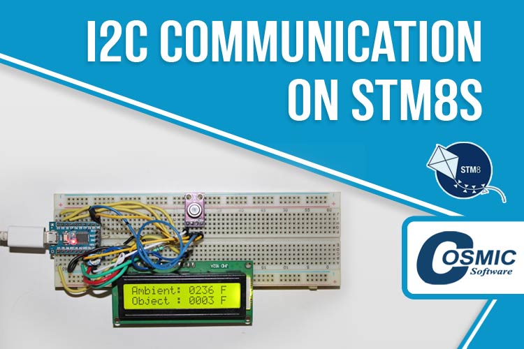
In this article, we are going to perform the I2C Communication on STM8S microcontroller by using the MLX90614 I2C sensor. We will measure the Ambient Temperature and the Object’s Temperature and then we will display the measured temperature on the LCD. If you are following the STM8S Microcontroller Tutorials, you would know that we have already covered the basics of the STM8s using the Cosmic C Compiler. So, let’s see what components will be required to perform the I2C communication on STM8S board.
Material Required to set-up I2C Communication on STM8S
We need the following components to perform the I2C communication on STM8S with MLX90614 I2C sensor.
- STM8S103F3P6 Development board
- ST-Link V2 programmer
- 16x2 LCD
- Potentiometers
- Connecting wires
- 1k resistor
- The MLX90614 Sensor Module
- Logic Analyzer (Recommended to get a better understanding)
Circuit Diagram to Interface MLX90614 and LCD with STM8S
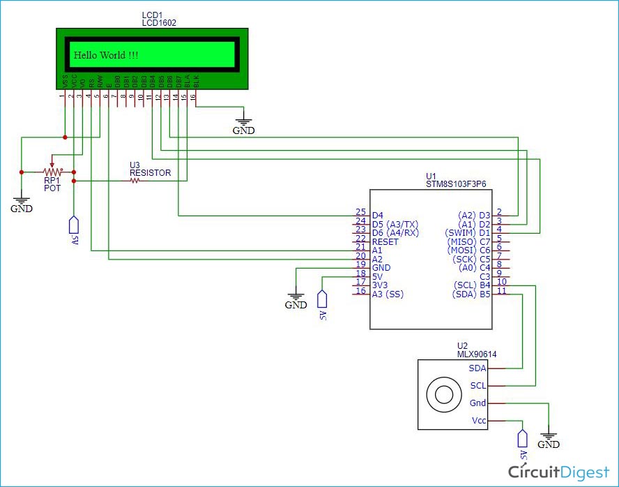
The following schematic illustrates the connections diagram of the MLX90614 sensor and the LCD with the STM8S. This schematic is very similar to the STM8S LCD tutorial that we have discussed previously. I have just wired the SDA and SCL pins of the sensor with the SDA (PB5) and SCL(PB4) pin of the STM8S103F3P6 board and I have provided a 5V power supply to both the sensor and the LCD. Please note carefully that we need to power the STM8S103F3P6 board with a USB connector so that the board gives a proper 5V power supply to both the sensor and the LCD.
I2C on STM8S103F3P6
We are going to use the Cosmic C compiler along with the SPL libraries. But I made another header file stm8s103_i2c.h that can be very useful to perform the I2C communication on the STM8S.
[upload this file from code folder on Cd and provide link]
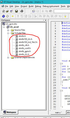
Make sure to click on the link to download the header file and add it to your project. If you have already read our previous articles on STM8S, then you might have an understanding on how to include a header file in the project directory. Otherwise check out the Getting Started with STM8S using STVD and Cosmic C Compiler article to know how to setup the programming environment and the compiler. Once you have done the setup for your project workspace, you should have the following header files that I have marked with red circle in the below image.
Please note that, I am not going to explain the theory of the I2C because we have already covered an article on I2C communication and you can follow the datasheet of any I2C devices to get more on the theory part. Here, we are going to discuss the functions that we have created in the “stm8s103_i2c.h” header file. And then we will be using the logic analyzer to see the working of the I2C communication in detail.
The “stm8s103_i2c.h” header file consists of the I2C_Setup() function. You can initialize the I2C by using this setup function. The CLK_GetClockFreq() function is used to get the CPU clock. It can be found in the “stm8s_clk.h” header file. The I2C_Init() function is defined in “stm8s_i2c.h” file. You can initialize the I2C protocol by using this function. This function takes some default parameters. You can right click on the function and then select the “Go to Definition of I2C_Init” option. It will redirect you to that particular destination where the function is defined.
void I2C_Setup(void)
{
                u8 Input_Clock = 0;
   Input_Clock = CLK_GetClockFreq()/1000000;
  I2C_Init(I2C_Speed, MLX90614_I2CADDR, I2C_DUTYCYCLE_2, I2C_ACK_CURR, I2C_ADDMODE_7BIT, Input_Clock);
}
Then we have a I2C_ByteWrite() function that allows us to write data on the slave register. This function will take two parameters. The I2C_Slave_Address is the address of the register where we want to write the data. And the iData is the data that we want to write on the target register. The I2C_GenerateSTART() is used to start the I2C. The I2C_Send7bitAddress() function is used to send the 7bit address of the slave.
void I2C_ByteWrite (u8 I2C_Slave_Address, u8 iData)
{
                I2C_GenerateSTART(ENABLE);
                while(!I2C_CheckEvent(I2C_EVENT_MASTER_MODE_SELECT));
                I2C_Send7bitAddress(I2C_Slave_Address, I2C_DIRECTION_TX);
                while(!I2C_CheckEvent(I2C_EVENT_MASTER_TRANSMITTER_MODE_SELECTED))
                I2C_SendData(iData);
                while(!I2C_CheckEvent(I2C_EVENT_MASTER_BYTE_TRANSMITTED));
                I2C_GenerateSTOP(ENABLE);
}
The I2C_ByteRead() function is used to read the value by using a particular register address. You can refer the datasheet of the I2C device to get the address of the registers. But you need to provide the instruction bit for the reading any I2C device and that can be done by adding “1” with the 7-bit device address of that I2C device. In my case, the device address is “0x5A” but at the top section of the “stm8s_i2c.h” header file, I have defined a “MLX90614_I2CADDR” Macro with the address of “0xB5”. This represents the device address with the extra read bit (i.e. “1” bit). The register address for the ambient temperature is “0x06” that is defined as the “MLX90614_TA” macro. And the “MLX90614_TOBJ1” macro represents the register address of the Object Temperature that is “0x07”. We will be using this macros as “ReadAddr” parameter in the “I2C_ByteRead()” function. The I2C_ReceiveData() function is used to receive the data and the data will be returned by the I2C_ByteRead() function in the pBuffer variable.
u8 I2C_ByteRead(uint8_t I2C_Slave_Address, uint8_t ReadAddr)
{
                u16 pBuffer;
                while(I2C_GetFlagStatus(I2C_FLAG_BUSBUSY));
                I2C_GenerateSTART(ENABLE);
                while(!I2C_CheckEvent(I2C_EVENT_MASTER_MODE_SELECT));
                I2C_Send7bitAddress(I2C_Slave_Address, I2C_DIRECTION_TX);
                while(!I2C_CheckEvent(I2C_EVENT_MASTER_TRANSMITTER_MODE_SELECTED));
                I2C_SendData((u8)(ReadAddr));
                while(!I2C_CheckEvent(I2C_EVENT_MASTER_BYTE_TRANSMITTED));
                I2C_GenerateSTART(ENABLE);
                while(!I2C_CheckEvent(I2C_EVENT_MASTER_MODE_SELECT));
                I2C_Send7bitAddress(I2C_Slave_Address, I2C_DIRECTION_RX);
                while(!I2C_CheckEvent(I2C_EVENT_MASTER_RECEIVER_MODE_SELECTED));
                while(!I2C_CheckEvent(I2C_EVENT_MASTER_BYTE_RECEIVED));
                pBuffer = I2C_ReceiveData();
                I2C_AcknowledgeConfig(I2C_ACK_NONE);
                I2C_GenerateSTOP(ENABLE);
                return pBuffer;
}
In the “main.c” file, we have a readTemperature(uint8_t a) function. It will take the targeted register address of the slave device and will return the measured value of the slave device. In my case, the address is already defined in the both “MLX90614_TA” and “MLX90614_TOBJ1” macros. The “MLX90614_Read()” function will print the value of both the ambient temperature and the object temperature.
uint16_t readTemperature(uint8_t a) {
   uint16_t res;
  res = I2C_ByteRead(MLX90614_I2CADDR, a);
  return res;
}
void MLX90614_Read(void)
{
                                uint16_t               temperature1;
                                uint16_t               temperature2;
                                temperature1 = readTemperature(MLX90614_TA);
                                delay_ms(20);
temperature2 = readTemperature(MLX90614_TOBJ1);
                                Lcd_Set_Cursor(1,10);
                                LCD_Print_Int(temperature1);
                                Lcd_Set_Cursor(2,10);
                                LCD_Print_Int(temperature2);
                                delay_ms(2000);
}
In the “main()” function, I have De-initialized the GPIO pins and the I2C first. Then you can find the “I2C_Setup()” function which I have declared in the “stm8s103_i2c.h” header file. There are some basic LCD command to initialize the LCD and clear the screen of the LCD. Then in the while loop, you can see that the MLX90614_Read() function has been called with a delay of 4 seconds.
main()
{
                /* Deinitializing the GPIOs and I2C */
                GPIO_DeInit(GPIOA);
                GPIO_DeInit(GPIOB);
                GPIO_DeInit(GPIOD);
                I2C_DeInit();
/* Initializing the I2C */
I2C_Setup();
                /* Initializing te LCD */
  Lcd_Begin();
                Lcd_Clear();
                Lcd_Set_Cursor(1,1);
                Lcd_Print_String("Initializing");
                Lcd_Set_Cursor(2,1);
                Lcd_Print_String("Wait...");
                delay_ms(1000);
                                Lcd_Clear();
                                Lcd_Set_Cursor(1,1);
                                Lcd_Print_String("Ambient:      F");
                                Lcd_Set_Cursor(2,1);
                                Lcd_Print_String("Object :      F");
                                delay_ms(100);
                while (1){
                                                MLX90614_Read();
                                                delay_ms(4000);
                }
}
Connecting Logic Analyzer with STM8S to Monitor I2C Communication
A logic analyzer is an electronic instrument that captures and displays multiple signals from a digital system or digital circuit. We are going to use the USB logic analyzer to analyze the I2C data. The connection of an USB logic analyzer is very simple. You can refer the following block diagram to connect an USB logic analyzer with any I2C devices to see the I2C data of that device.
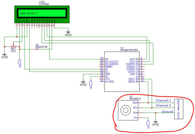
As you can see in the above diagram, you need to connect the SDA and SCL pin of the I2C device with any two channels of the logic analyzer. And the ground pin is need to be connected to the ground pin of the I2C device. You can refer the red circled area on the above schematic.
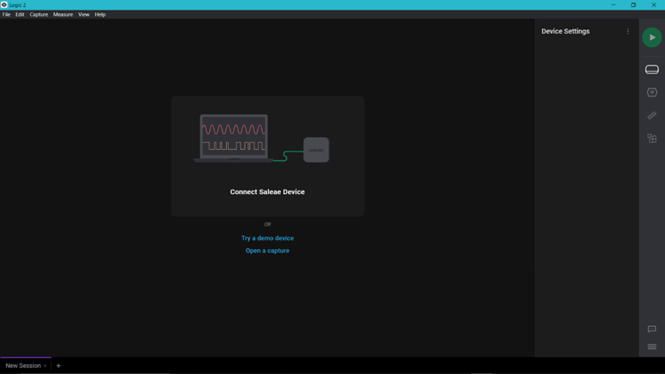
We have some interesting Logic Software’s on the internet to visualize the data coming from the logic analyzer. In my case, I used the “Saleae Logic” software. You need to install this software. When you open the Logic software, you will see a grey box with some instruction which states that you need to connect the USB logic analyzer to your laptop. So, connect the Logic Analyzer with the USB port. When you connect your Logic Analyzer to your laptop, you will be able to see that some channels are opened in the left side of the window. You can refer the second picture when you have connected your logic analyzer to the laptop.
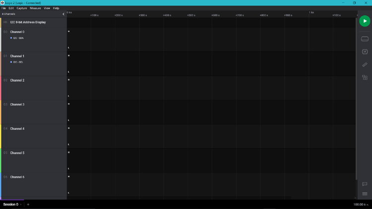
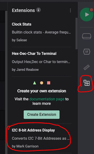
The red marked area in the picture given below represents the menu section of the Logic Analyzer. You can start the analyzer by using that green play button. We have a Device Settings, Analyzers, Timing Markers and Measurement and an Extension Buttons under the Play button.

You need to click on the “Extension” button and then search for an extension named as “I2C 8-bit Address Display” and install this extension. When you have installed this extension, it will be displayed in the extension section. You can refer the second picture for the extension.
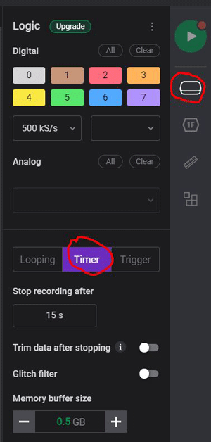
Then you need to go to the Device Setting as I have marked in the red under the green play button. You will see a window as shown in the below picture. You have to set the timer. In my case, I have setup the timer for 15 second. That means the analyzer will take the readings for 15 seconds when we will click the Play button.
When you will complete the device setting, you need to go to the analyzer section by clicking on the analyzer button that you can find under the device setting button. The image given below refers to the Analyzer section. This section will be empty for you when you will open this for the first time. You need to click on the “Plus” sign at the top right corner of the analyzer section.
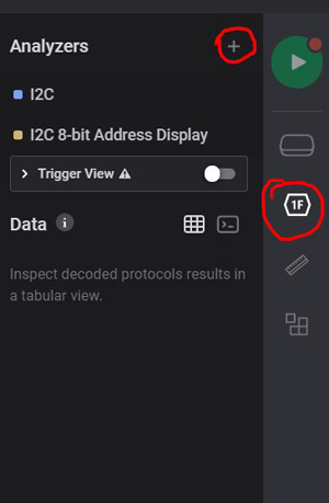
Thereafter, you will get a search window as you can see in the image below. Select the “I2C” and then again click on that “Plus” sign and select the “I2C 8-bit Address Display”, the extension that you have already installed before. Now, we are ready to use the Logic Software and the USB logic analyzer. So, connect the Logic analyzer and connect the STM8S board to the another USB port. We are using the USB port to power the STM8S board so that STM8S can power the sensor and the LCD both. When you will connect the Logic analyzer and the STM8s board, you will see that the LCD is displaying the Ambient temperature and the Object Temperature. But you need to press on the Play button on the Logic software and then you need to press the reset button that is present on the STM8S board. Now, you can see that the logic analyzer gets the reading of the I2C data. Now, wait for the 15 seconds.

After 15 seconds, you can see some output as the shown in the above image. The red circle refers to the I2C communication. Double click to zoom this part. When you zoom in this section, you will get some pulse data as you can see in the below image.

In the above image, I have mentioned highlighted some parts with colored circles so that you can easily understand how to read data with a Logic analyzer. The pink circle refers to the I2C device address (i.e. 0x5A) with “W” for write mode or “R” for read mode. Then we have the blue circle which indicates the targeted register addresses. The targeted registers were “0x06” for Ambient temperature and “0x07” for object temperature. The green and red circles indicate the data that we have received from the targeted registers. When I took the picture, the data for the ambient temperature was “0x48” and for the object temperature, the data was “0x55”. You need to convert this hex data into a decimal value. You can cross check this hex data with the decimal value that is displayed on the LCD. I hope you have understood the I2C with the STM8s and how to analyze the I2C with an USB logic analyzer.
Output of the I2C on STM8S and Displaying on LCD
As you can see in the following images, the LCD displays the output as we expected. I have removed the logic analyzer while taking the following images. You can see that when we powere up the system, the LCD shows a string as “Initializing wait …”. Then it displays the measured temperature for both the ambient and object after 1 second, as you can see in the second image below. I did not apply the required conversions and error checks because my focus was more on the I2C part. You can do these things by following the instructions from the dataset.
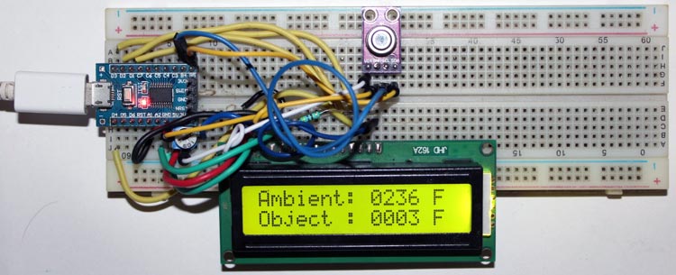
The working of this project is also sown in the video linked below. If you have any questions, leave them in the comment section or use our forums for other technical queries.
Complete Project Code
#define LCD_RS     GPIOA, GPIO_PIN_1
#define LCD_EN      GPIOA, GPIO_PIN_2
#define LCD_DB4    GPIOD, GPIO_PIN_1
#define LCD_DB5    GPIOD, GPIO_PIN_2
#define LCD_DB6    GPIOD, GPIO_PIN_3
#define LCD_DB7    GPIOD, GPIO_PIN_4
#include "stm8s.h"
#include "stm8s_i2c.h"
#include "stm8s_gpio.h"
#include "stm8s103_lcd_16x2.h"
#include "stm8s103_i2c.h"
void delay (int ms) //Function Definition
{
int i =0 ;
int j=0;
for (i=0; i<=ms; i++)
{
for (j=0; j<120; j++) // Nop = Fosc/4
_asm("nop"); //Perform no operation //assembly code
}
}
void GPIO_setup(void)
{
     GPIO_DeInit(GPIOA);
GPIO_DeInit(GPIOB);
GPIO_DeInit(GPIOD);
    GPIO_Init(GPIOB, GPIO_PIN_4, GPIO_MODE_OUT_OD_HIZ_FAST);
    GPIO_Init(GPIOB, GPIO_PIN_5, GPIO_MODE_OUT_OD_HIZ_FAST);
}
/*
Function: readTemperature
Description: Takes the register address and return the temperatur value.
*/
uint16_t readTemperature(uint8_t a) {
   uint16_t res;
  res = I2C_ByteRead(MLX90614_I2CADDR,a);
  return res;
}
void MLX90614_Read(void){
uint16_t temperature1;
uint16_t temperature2;
temperature1 = readTemperature(MLX90614_TA);
delay_ms(20);
  temperature2 = readTemperature(MLX90614_TOBJ1);
Lcd_Set_Cursor(1,10);
LCD_Print_Int(temperature1);
Lcd_Set_Cursor(2,10);
LCD_Print_Int(temperature2);
delay_ms(2000);
}
main()
{
/* Deinitializing the GPIOs and I2C */
GPIO_DeInit(GPIOA);
GPIO_DeInit(GPIOB);
GPIO_DeInit(GPIOD);
I2C_DeInit();
/* Initializing the I2C */
I2C_Setup();
/* Initializing te LCD */
  Lcd_Begin();
Lcd_Clear();
Lcd_Set_Cursor(1,1);
Lcd_Print_String("Initializing");
Lcd_Set_Cursor(2,1);
Lcd_Print_String("Wait...");
delay_ms(1000);
Lcd_Clear();
Lcd_Set_Cursor(1,1);
Lcd_Print_String("Ambient:      F");
Lcd_Set_Cursor(2,1);
Lcd_Print_String("Object :      F");
delay_ms(100);
while (1){
MLX90614_Read();
delay_ms(4000);
}
}

