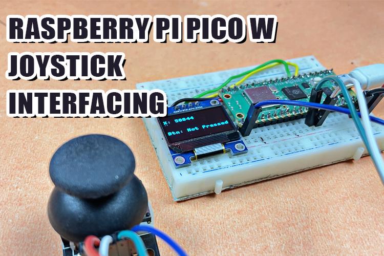
Welcome to our comprehensive blog, where we will interface the Raspberry Pi Pico W with an Analog Joystick Module. This blog post serves as a professional guide, offering step-by-step instructions on how to establish a connection and effectively take input from the joystick using the powerful Raspberry Pi Pico W board.
Before this, we have learned to interface Joystick Module with Arduino, Joystick Module with Arduino Leonardo, Joystick Module with PIC Microcontroller, Joystick Module with Raspberry Pi, Joystick Module with AVR Microcontroller.
The components we will require for this project are
- Raspberry Pi Pico W
- Joystick Module
- Breadboard
- Jumper wires
- LED display (not mandatory)
Joystick Module Pinout
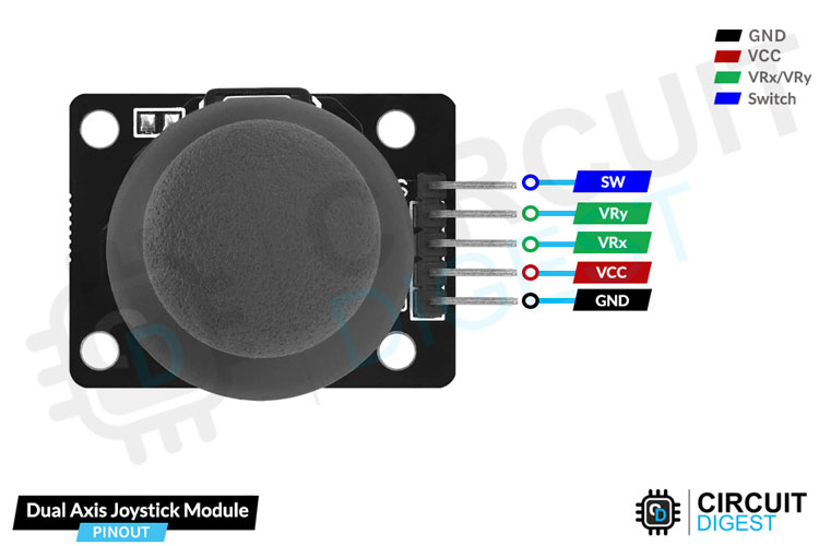
The joystick module typically comes with five pins, and their pinout configuration is as follows:
VCC This pin connects to the power supply, usually +5V from the microcontroller or development board.
GND This pin is connected to the ground (0V) of the power supply and serves as the reference voltage for the module.
VRx This pin represents the analog output for the X-axis of the joystick. It provides a variable voltage proportional to the joystick's horizontal movement.
VRy This pin is similar to VRx but represents the analog output for the Y-axis of the joystick, providing a variable voltage corresponding to the joystick's vertical movement.
SW This is the switch pin of the joystick module. When the joystick is pressed down, this pin is pulled low (grounded). Otherwise, it remains at a high voltage level (usually VCC).
Commonly Asked Questions about Joystick Module
Can I use multiple joysticks simultaneously?
Yes, you can use multiple joysticks simultaneously by connecting them to different analog input pins of the microcontroller. By reading the values from each joystick independently, you can control multiple axes or devices simultaneously in your project.
What are the different types of joystick available?
There are various types of joysticks designed for different applications, such as gaming, robotics, aviation, and industrial control. Some common types include analog joysticks (potentiometer-based), digital joysticks (using switches or encoders), thumbsticks, flight sticks, and arcade-style joysticks.
In this tutorial, we are using an analog joystick.
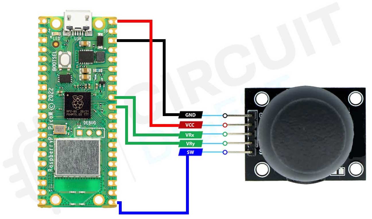
Circuit Diagram - Interface Raspberry Pi Pico W with Joystick Module
Connect the VCC pin of the joystick module to the Vbus pin on the Raspberry Pi Pico W.
Connect the GND pin of the joystick module to the GND (ground) pin on the Raspberry Pi Pico W.
Connect the VRx pin of the joystick module to one of the analog input pins on the Raspberry Pi Pico W (e.g., ADC0).
Connect the VRy pin of the joystick module to another analog input pin on the Raspberry Pi Pico W (e.g., ADC1).
Now let’s move on to the software setup for programming it.
Programming Raspberry Pi for Joystick with Micropython
- First open the thonny ide.
- Download micropython firmware for raspberry pi pico W from official website.
- Go to tools> options>interpreter and select raspberry pi pico as interpreter.
- Copy paste the below code in thonny ide and save it in your board.
The below code explains the interfacing of the raspberry pi pico W with an analog joystick and then printing it on screen.
from machine import Pin, ADC
import utime
In this section, we import necessary modules: Pin and ADC from the machine module for GPIO and ADC (Analog-to-Digital Converter) functionality, and utime for working with time functions.
xAxis = ADC(Pin(27))
yAxis = ADC(Pin(26))
button = Pin(16, Pin.IN, Pin.PULL_UP)
Here, we create three objects: xAxis, yAxis, and button. We set up the xAxis and yAxis objects to read analog values from the pins 27 and 26, respectively, using the ADC constructor. We also set up the button object to read digital input from pin 16. The Pin.IN argument sets the pin mode to input, and Pin.PULL_UP enables the internal pull-up resistor to keep the pin at a high level when the button is not pressed.
while True:
This is a loop that will run indefinitely. The code inside the loop will be executed repeatedly until the program is stopped.
    xValue = xAxis.read_u16()
    yValue = yAxis.read_u16()
    buttonValue = button.value()
In this section, we read the analog values from the xAxis and yAxis objects using the read_u16() method. The method returns the raw 16-bit analog values from the respective pins. We also read the digital input from the button object using the value() method, which returns 0 if the button is pressed and 1 if it is not pressed.
print("X Value:", xValue, "Y Value:", yValue, "Button Value:", buttonValue)
Here, we print the raw analog values for xValue and yValue, as well as the digital value for buttonValue to the console. This will display the values continuously every 0.1 seconds.
utime.sleep(0.1)
The utime.sleep(0.1) function pauses the execution of the code for 0.1 seconds before starting the next iteration of the loop. This creates a small delay between each reading and printing of the values, preventing excessive CPU usage.
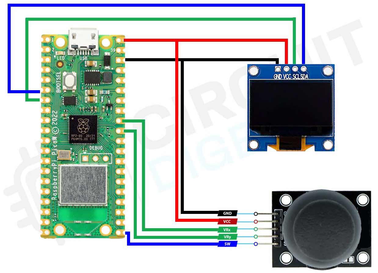
Circuit Diagram - Interface Joystick Module with Raspberry Pi Pico W and OLED Display
Below is the circuit diagram for the same:-
The below code explains taking input from the analog joystick and printing it on an OLED display. For more info about OLED interfacing, you can read interfacing Pico W with OLED blog on our website.
Code Explanation of Joystick with OLED
from machine import Pin, ADC, SoftI2C
import ssd1306
import utime
These lines import the necessary modules: Pin, ADC, and SoftI2C from the machine module for GPIO, Analog-to-Digital Converter, and I2C communication functionality. ssd1306 for controlling the OLED display. utime for working with time functions.
i2c = SoftI2C(scl=Pin(5), sda=Pin(4))
Here, we create an i2c object using SoftI2C, which sets up a software-based I2C communication protocol. We specify the SCL (clock) pin as Pin 5 and the SDA (data) pin as Pin 4. These pins are used for communication between the Raspberry Pi Pico and the SSD1306 OLED display.
xAxis = ADC(Pin(27))
yAxis = ADC(Pin(26))
button = Pin(16, Pin.IN, Pin.PULL_UP)
This section sets up the joystick by creating three objects:
xAxis: It reads analog values from Pin 27 using ADC.
yAxis: It reads analog values from Pin 26 using ADC.
button: It reads digital input from Pin 16. The pin mode is set to input (Pin.IN), and an internal pull-up resistor is enabled (Pin.PULL_UP), which keeps the pin at a high level when the button is not pressed.
oled_width = 128
oled_height = 64
oled = ssd1306.SSD1306_I2C(oled_width, oled_height, i2c)
In these lines, we set the width and height of the OLED display (128x64 pixels) and create an oled object using SSD1306_I2C. This initializes the OLED display with the specified dimensions and I2C communication.
while True:
This is a loop that will run indefinitely. The code inside the loop will be executed repeatedly until the program is stopped.
    xValue = xAxis.read_u16()
    yValue = yAxis.read_u16()
    buttonValue = button.value()
In this section, we read the analog values from xAxis and yAxis using the read_u16() method, which returns the raw 16-bit analog values from the respective pins. We also read the digital input from the button using the value() method, which returns 0 if the button is pressed and 1 if it is not pressed.
oled.fill(0)
Here, we clear the OLED display by filling it with black (0) pixels.
    oled.text("X: {}".format(xValue), 0, 0)
    oled.text("Y: {}".format(yValue), 0, 20)
In this section, we use the text() method to display the analog values from xValue and yValue on the OLED display. The text will be shown at coordinates (0, 0) for X-axis and (0, 20) for Y-axis.
    if buttonValue == 0:
        oled.text("Btn: Pressed", 0, 40)
    else:
        oled.text("Btn: Not Pressed", 0, 40)
This conditional statement checks the value of buttonValue. If it is 0 (button is pressed), it displays "Btn: Pressed" on the OLED at coordinates (0, 40). Otherwise, it displays "Btn: Not Pressed" at the same coordinates.
oled.show()
After setting up the display with text and images, the show() method is used to update the OLED display, making the changes visible on the screen.
utime.sleep(0.1)
The utime.sleep(0.1) function pauses the execution of the code for 0.1 seconds before starting the next iteration of the loop. This creates a small delay between each reading and updating of the values on the OLED, preventing excessive CPU usage. The loop then repeats, continuously updating the OLED display with new joystick values and button status.
Projects using Joystick Module
Dive into nostalgia with our DIY Tetris Game using Arduino and OLED Display. Learn coding, crafting, and electronics as we guide you through creating your own handheld classic. Join the fun and bring retro gaming to life in this exciting blog series.
Unlock the world of sound sensing technology with our guide to the KY-038 Sound Sensor. Discover its inner workings and learn how to seamlessly interface it with the ESP32 microcontroller. Elevate your projects by incorporating an OLED display for visual feedback. Dive into this hands-on tutorial where we break down complex concepts into simple steps. Join us and explore the exciting realm of sound-responsive innovations!
Step into the world of ESP32 and OLED integration. Our straightforward tutorial will walk you through the process, allowing you to effortlessly connect and display content on the OLED screen using the ESP32. No jargon, just simple steps to bring your project to life. Join us in exploring this exciting synergy between hardware components!
Complete Project Code
Code for Joystick with Pico W

from machine import Pin, ADC
import utime
xAxis = ADC(Pin(27))
yAxis = ADC(Pin(26))
button = Pin(16, Pin.IN, Pin.PULL_UP)
while True:
    xValue = xAxis.read_u16()
    yValue = yAxis.read_u16()
    buttonValue = button.value()
    print("X Value:", xValue, "Y Value:", yValue, "Button Value:", buttonValue)
    utime.sleep(0.1)
Code for Joystick with Pico W and OLED

from machine import Pin, ADC, SoftI2C
import ssd1306
import utime
i2c = SoftI2C(scl=Pin(5), sda=Pin(4))
xAxis = ADC(Pin(27))
yAxis = ADC(Pin(26))
button = Pin(16, Pin.IN, Pin.PULL_UP)
oled_width = 128
oled_height = 64
oled = ssd1306.SSD1306_I2C(oled_width, oled_height, i2c)
while True:
    xValue = xAxis.read_u16()
    yValue = yAxis.read_u16()
    buttonValue = button.value()
    oled.fill(0)
    oled.text("X: {}".format(xValue), 0, 0)
    oled.text("Y: {}".format(yValue), 0, 20)
    if buttonValue == 0:
        oled.text("Btn: Pressed", 0, 40)
    else:
        oled.text("Btn: Not Pressed", 0, 40)
    oled.show()
    utime.sleep(0.1)

