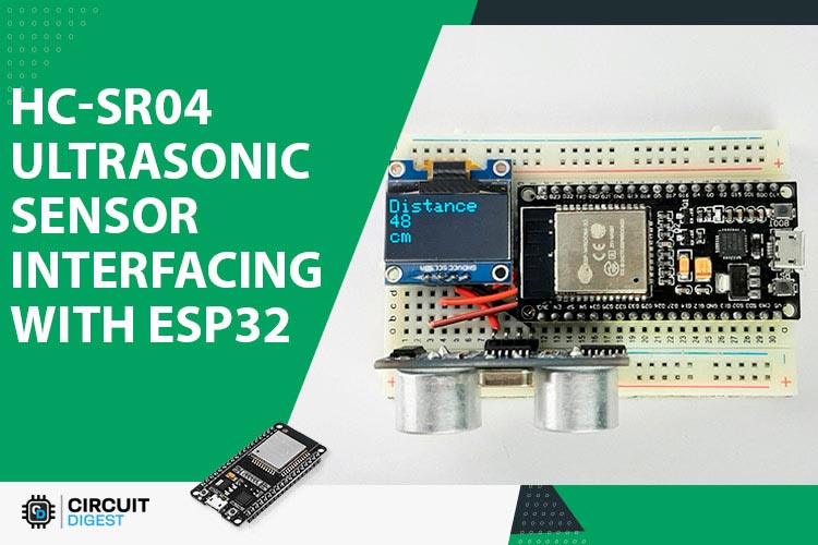
If you are an electronics engineer or a beginner and want to build an obstacle avoidance robot, you need to first learn how an obstacle avoidance system works! which makes this project of ours super important, because in this project we are going to interface a HC-SR04 Ultrasonic Distance Sensor module with ESP32 and we are going to know every little detail about the module, which is a key component of any obstacle avoidance or detection system. So, in this project, we are going to know every little detail about the HC-SR04 Ultrasonic Distance Sensor module along with interfacing it with ESP32. The HC-SR04 ultrasonic sensor has a detection range of 13 feet with an angle of 15 degrees, which is great for detecting obstacles. Other than that, it has a very low operating current so it's very suitable for battery-powered applications.
In our previous attempts, we have used this HC-SR04 with an Arduino and PIC microcontroller to build many interesting projects, some of which are linked below.
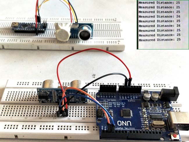
- Distance Measurement using Ultrasonic Sensor and Arduino
- Interfacing Ultrasonic Sensor HC-SR04 with PIC Microcontroller
- Raspberry Pi Based Obstacle Avoiding Robot using Ultrasonic Sensor
- IoT Based Dumpster Monitoring using Arduino & ESP8266
HC-SR04 Ultrasonic Sensor Pinout
The HC-SR04 ultrasonic proximity sensor module has 4 pins; those are VCC, Trig, Echo, and Gnd. The input and output of this sensor are digital so we need to connect it to the digital pin of the microcontroller. The pinout of the HC-SR04 is shown below.
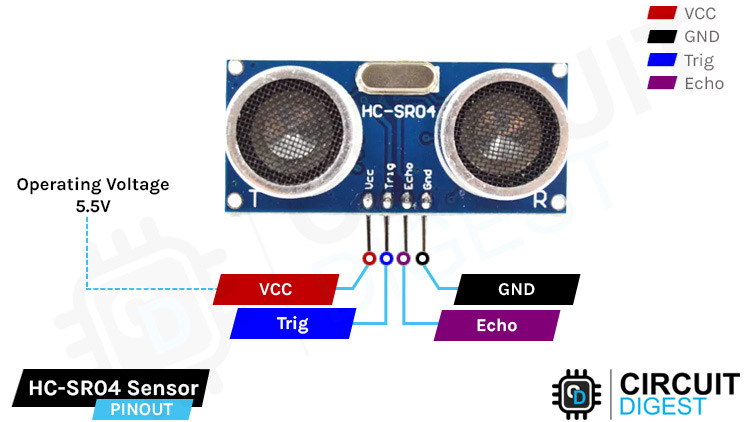
VCC The supply pin of the HC-SR04 Module. Connect it to the 5V pin of the ESP32.
Trig This is the trigger pin of the HC-SR04 module. By setting this pin to HIGH for 10µs, the sensor initiates an ultrasonic burst.
Echo This is the echo pin of the HC-SR04 sensor module. This pin remains high until the sensor receives the echo back or a timeout occurs.
GND This is the Ground pin of the module, connect it to the ground pin of the ESP32.
HC-SR04 Ultrasonic Sensor Overview
Before we go and understand how the ultrasonic distance sensor works, we will first learn what ultrasound is: ultrasound sound is a high-pitched wave, in which the frequency of the wave exceeds the audible hearing range of humans. The audible range for humans is 20Hz to 20Khz, and the sound emitted from the module is way higher than what human ears can process so it's inaudible for humans.
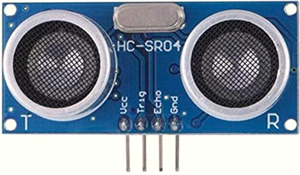
An ultrasonic distance sensor consists of two ultrasonic transducers; one acts as a transmitter with 40Khz frequency, and the other one acts as a receiver and listens to the reflected received pulses. The sensor produces an output pulse that is proportional to the distance of the object in front of the sensor. By reading the pulse width with a microcontroller, one can determine the distance of the object the sensor has an operating voltage of 5 volts and can provide excellent non-contact range detection between 2cm to 400cm. Ultrasonic sensor can be interfaced with any microcontroller, you can find all the interfacing of Ultrasonic sensor by following the link.
How does HC-SR04 Ultrasonic Distance Sensor work?
To start the distance measurement process we need to set the trigger pin high for 10uS. In response, the sensor transmits an ultrasonic burst of eight pulses at 40KHz. The eighth pulse is so designed that the receiver can distinguish between the transmitted pulse from ambient ultrasound. When the 8-pulse transmission process is finished, the echo pin goes high indicating the return signal. If those transmitted signals do not return after 38ms that means there is no obstruction present in front of the sensor.
If those pulses are reflected back, the echo pin goes low as soon as the signal is received, and that generates a pulse on the echo pin whose width varies from 150us to 25ms depending on the time taken to receive the signal.
Calculating the Distance by measuring the pulse width
The received pulse width can be used to determine the distance from the reflected object, we can do this with the distance-speed-time equation. Let's assume we have an unknown distance X, for which we have received 700us pulse width on the echo pin. Now to calculate the distance we will use the following formula.
Distance = Speed x Time
Now we know the speed of sound is 343.2 m/s. To calculate the distance we need to convert the speed of sound to cm/us which will be 0.03432 cm/uS, and we also know the time value received from the ultrasonic sensor which is 700uS.
Distance = (0.03432 cm/us x 700uS) / 2 = 12.012 cm
Now we know that the object is 12.012 cm away from the sensor.
Commonly Asked Questions about HC-SR04 Ultrasonic Range Sensor Module
Q. What is the maximum range of HC-SR04?
The Maximum range of the HC-SR04 is 400cm or 13 feet.
Q. Can HC SR04 detect water?
Yes, this sensor is able to detect water surface altitude, which can be used as an early indication of the flood. There are a lot of projects available on the internet with water surface-level detection systems using ultrasonic sensors and the ESP8266-12E module.
Q. Is the ultrasonic sensor HC-SR04 waterproof?
The HC-SR04 module is very fragile and can easily be damaged by dirt, or even high winds, and above all it's not waterproof. But there are specific modules available in the market that are designed with some level of water resistance and can be used in highly humid environments.
Q. Does HC SR04 work with 3.3 V?
According to the datasheet, it cannot be powered from 3.3V but what you can do is trigger the module with 3.3V and in the echo line use a suitable voltage divider to drop the voltage to 3.3V.
ESP32 with HC-SR04 Ultrasonic Sensor Circuit Diagram
Now that we have a complete understanding of how the HC-SR04 ultrasonic module works, we have connected all the necessary wires to the ESP32 module and will write a simple code and test the module and its workings.
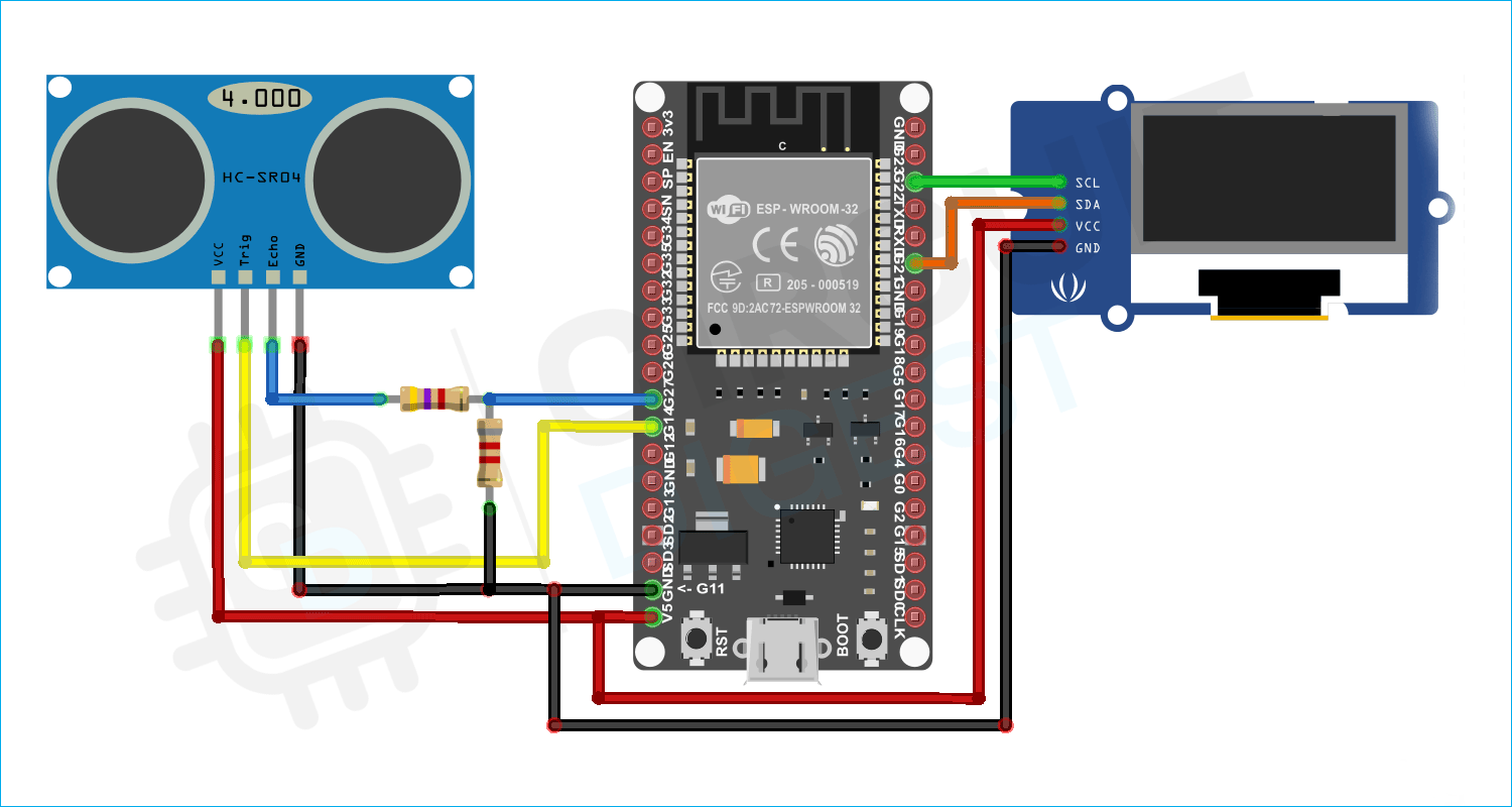
The complete test schematic of interfacing the HC-SR04 sensor with ESP32 is shown below.
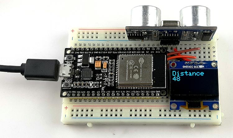
As you can see in the image above we have connected the HC-SR04 module and an OLED module to the ESP32. The connection process is very simple as the ultrasonic module works with 5V so we have used a voltage divider in the echo pin to reduce the 5V output to 3.3V output. For the HC-SR04 module, any digital pin of the ESP32 can be used as I/O but for the OLED model, you need to use the I2C pin which is the IO21 and IO22 of the ESP32 module. That's all for the connection process; the hardware image below will give you a better idea of the circuit connection.
Arduino Code for Interfacing HC-SR04 Sensor with ESP32
In this section of the article, we will be describing the code which will be used to measure the distance with the HC_SR04 sensor and display it to the 128X64 display. But before we start the coding process, we need to install the Adafruit_GFX library, Adafruit_SSD1306.h, and NewPing.h library from the library manager of Arduino to process the data from the sensor and display.
We start our code by including all the required libraries, which are the Adafruit_GFX library and the NewPing library. The Adafruit_GFX library has SPI and Wre library as dependencies, so we need to include those libraries before including Adafruit_GFX library.
#include <SPI.h>
#include <Wire.h>
#include <Adafruit_GFX.h>
#include <Adafruit_SSD1306.h>
#include "NewPing.h"
Next, we have defined the Trigger pin and the echo pin of the HC-SR04 sensor. We have also defined the max theoretical distance that this sensor can measure.
#define TRIGGER_PIN 14
#define ECHO_PIN 27
// Maximum distance we want to ping for (in centimeters).
#define MAX_DISTANCE 400
Next, we have defined the screen width and screen height for our sensor. We also defined the OLED Reset parameter which is required by the library.
#define SCREEN_WIDTH 128 // OLED display width, in pixels
#define SCREEN_HEIGHT 64 // OLED display height, in pixels
// Declaration for an SSD1306 display connected to I2C (SDA, SCL pins)
#define OLED_RESET     -1 //
Next, we have two instances for the NewPing library and you need to first learn how an obstacle avoidance system works! which makes this project of ours super important, because in this project we are going to interface a HC-SR04 Ultrasonic Distance Sensor module with ESP32 and we are going to know every little detail about the module, which is a key component of any obstacle avoidance or detection system. library and have passed all the parameters that we have declared previously.
NewPing sonar(TRIGGER_PIN, ECHO_PIN, MAX_DISTANCE);
Adafruit_SSD1306 display(SCREEN_WIDTH, SCREEN_HEIGHT, &Wire, OLED_RESET);
Next, we have our setup function. In the setup function, we enable the serial with 115200 baud and we also use the display.begin method to initialize the OLED display. By checking the return of the display.begin method we can be sure if the ESP is able to detect the display or not, that's all is there in the setup() function.
void setup() {
  Serial.begin(115200);
  // SSD1306_SWITCHCAPVCC = generate display voltage from 3.3V internally
  if (!display.begin(SSD1306_SWITCHCAPVCC, 0x3C)) {
    Serial.println(F("SSD1306 allocation failed"));
    for (;;); // Don't proceed, loop forever
  }
}
Next, we have our loop() function, in the loop function, we print the measured distance data to vary the accuracy and we call the update_display() function, which we have defined in the next section.
void loop() {
  Serial.print("Distance = ");
  Serial.print(sonar.ping_cm());
  Serial.println(" cm");
  delay(300);
  update_display();
}
Next, we have our update display function. In this function, we have first cleared the display set, increased the text size, set the display color to white, and printed the data on the display.
void update_display(){
  display.clearDisplay();
  display.setTextSize(2);
  delay(1);
  display.setTextColor(WHITE);
  delay(1);
  display.println(F("Distance"));
  delay(1);
  display.println(sonar.ping_cm());
  delay(1);
  display.println("cm");
  delay(1);
  display.display();
  delay(500);
}
This marks the end of our coding function, and we can move to the next section where we have tested our code.
HC-SR04 Ultrasonic Range Sensor with ESP32 Working
The gif image below shows the working of the HC-SR04 Ultrasonic Range Sensor module. As we have discussed earlier, we have programmed the ESP32 so that the display gets updated every time new distance data is available to the esp32. To test that, we have moved an object in front of the sensor, and you can see that the distance data gets updated on the display.
Troubleshooting HC-SR04 Ultrasonic Sensor Module
If you are having trouble interfacing the HC-SR04 with ESP32, you first need to check the power line. The ultrasonic sensor module works with a 5V supply, and if you're powering it with 3.3V, the module will be unstable.
The module can give you inaccurate information if you are working with an unsupported library for your module, so you need to check the library that you have installed or you need to install the proper library for the module.
If the module is still not working, try comparing your module with another one.
Projects using HC-SR04 Ultrasonic Sensor Module
If your objective is to learn how to interface HC-SR04 ultrasonic modules with Raspberry Pi, then this project is for you because in this project we have used the Raspberry pi module to demonstrate the working of the HC-SR04 module.
If you are trying to interface the HC-SR04 module with a PIC microcontroller then this project is what you are looking for, because in this project not only we have interfaced the PIC microcontroller with HC-SR04 but we have also measured the distance with this setup.
If you are searching for some interesting project online then this is what you are looking for, because in this project we have tried to calculate the distance between two ultrasonic sensors so that we can double the range of this sensor.
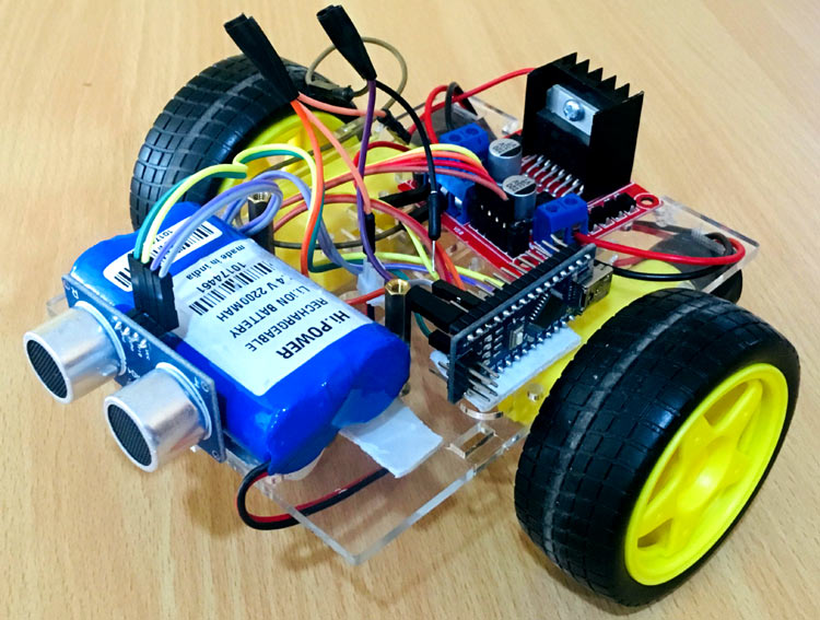
If you are looking for some interesting robot ideas, this project is for you because in this project we have built a simple obstacle avoidance robot using an ultrasonic sensor.
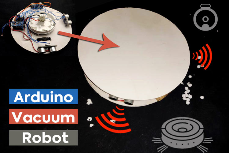
If you are looking for a simple, interesting, and useful electronic project then this project is for you because in this project we have used the popular HC-SR04 ultrasonic sensor to build a vacuum cleaning robot using an Arduino.
Complete Project Code
// Include NewPing Library

#include <SPI.h>
#include <Wire.h>
#include <Adafruit_GFX.h>
#include <Adafruit_SSD1306.h>
#include "NewPing.h"

// Hook up HC-SR04 with Trig to Arduino Pin 9, Echo to Arduino pin 10
#define TRIGGER_PIN 14
#define ECHO_PIN 27

// Maximum distance we want to ping for (in centimeters).
#define MAX_DISTANCE 400

#define SCREEN_WIDTH 128 // OLED display width, in pixels
#define SCREEN_HEIGHT 64 // OLED display height, in pixels

// Declaration for an SSD1306 display connected to I2C (SDA, SCL pins)
#define OLED_RESET     -1 // Reset pin # (or -1 if sharing Arduino reset pin)

// NewPing setup of pins and maximum distance.
NewPing sonar(TRIGGER_PIN, ECHO_PIN, MAX_DISTANCE);

Adafruit_SSD1306 display(SCREEN_WIDTH, SCREEN_HEIGHT, &Wire, OLED_RESET);


void setup() {
  Serial.begin(115200);

  // SSD1306_SWITCHCAPVCC = generate display voltage from 3.3V internally
  if (!display.begin(SSD1306_SWITCHCAPVCC, 0x3C)) {
    Serial.println(F("SSD1306 allocation failed"));
    for (;;); // Don't proceed, loop forever
  }
}

void loop() {

  Serial.print("Distance = ");
  Serial.print(sonar.ping_cm());
  Serial.println(" cm");
  delay(300);
  update_display();
}

void update_display()
{
  display.clearDisplay();

  display.setTextSize(2);
  delay(1);
  display.setTextColor(WHITE);
  delay(1);
  display.println(F("Distance"));
  delay(1);
  display.println(sonar.ping_cm());
  delay(1);
  display.println("cm");
  delay(1);
  display.display();
  delay(500);
  ESP.restart();
}
