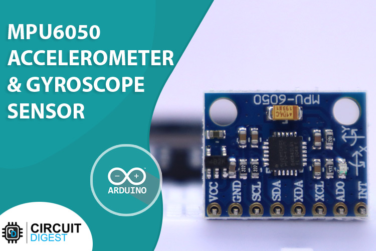
The MPU6050 is a very popular accelerometer gyroscope chip that has six axes sense with a 16-bit measurement resolution. This high accuracy in sense and the cheap cost make it very popular among the DIY community. Even many commercial products are equipped with the MPU6050. The combination of gyroscope and accelerometers is commonly referred to as an Inertial Measurement Unit or IMU.
IMU sensors are used in a wide variety of applications such as mobile phones, tablets, satellites, spacecraft, drones, UAVs, robotics, and many more. They are used for motion tracking, orientation and position detection, flight control, etc.
MPU6050 Module Pinout
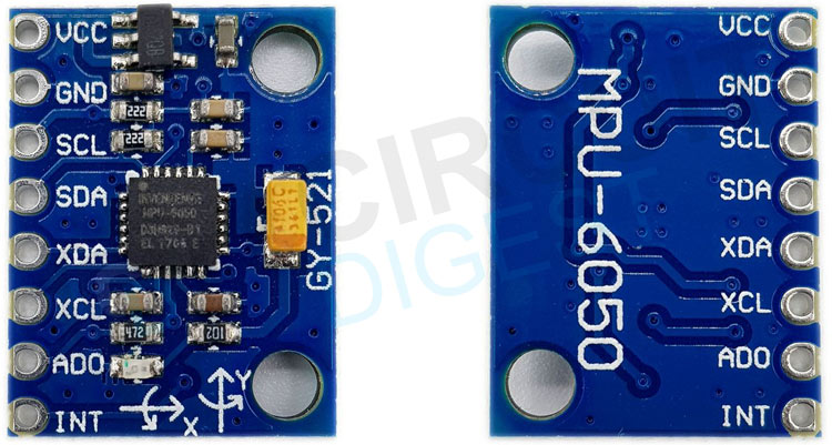
The MPU6050 module has a total of 8 pins. In which at least 4 pins are necessary for the interfacing. The pinout of a MPU6050 module is as follows:
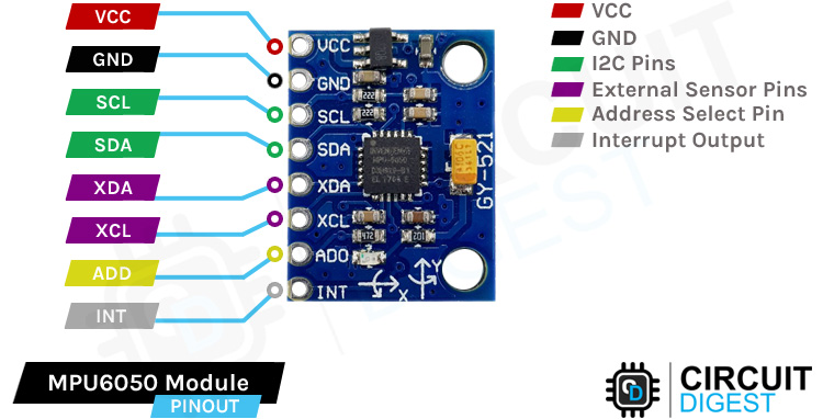
VCC Provides power for the module, Connect to the 5V pin of the Arduino.
GND Ground Connected to Ground pin of the Arduino.
SCL Serial Clock Used for providing clock pulse for I2C Communication.
SDA Serial Data Used for transferring Data through I2C communication.
XDA Auxiliary Serial Data - Can be used to interface other I2C modules with MPU6050.
XCL Auxiliary Serial Clock - Can be used to interface other I2C modules with MPU6050.
ADD/ADO Address select pin if multiple MPU6050 modules are used.
INT Interrupt pin to indicate that data is available for MCU to read.
MPU6050 Module Parts
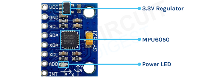
The MPU6050 module consists of an MPU6050 IMU chip from TDK InvenSense. It comes in a 24-pin QFN package with a dimension of 4mm x 4mm x 0.9mm. The module has a very low component count, including an AP2112K 3.3V regulator, I2C pull-up resistors, and bypass capacitors. There is also a power led which indicates the power status of the module.
MPU6050 Gyroscope Sensor Module Circuit Diagram
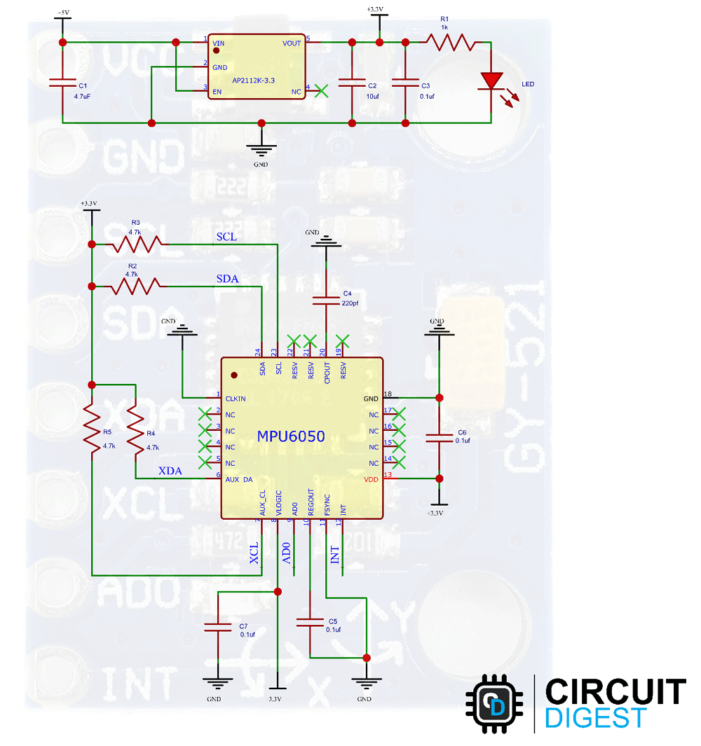
The schematic diagram of MPU6050 module is given below. As mentioned earlier, the board has a very low components count. The power section is designed around the AP2112K-3.3 voltage regulator. Sufficient filtering is provided with the tantalum and multilayer capacitors. An LED with a current limit resistor is used as a power indicator.
The MPU6050 circuitry is pretty simple. It consists of the MPU6050 chip itself with the bypass capacitors and the pull-up resistors.
How does MPU6050 Module Work?
The MPU6050 is a Micro-Electro-Mechanical Systems (MEMS) that consists of a 3-axis Accelerometer and 3-axis Gyroscope inside it. This helps us to measure acceleration, velocity, orientation, displacement and many other motion-related parameters of a system or object. This module also has a (DMP) Digital Motion Processor inside it which is powerful enough to perform complex calculations and thus free up the work for Microcontroller.
The module also has two auxiliary pins which can be used to interface external IIC modules like a magnetometer, however, it is optional. Since the IIC address of the module is configurable more than one MPU6050 sensor can be interfaced to a Microcontroller using the AD0 pin. This module also has well documented and revised libraries available hence it’s very easy to use with famous platforms like Arduino. So, if you are looking for a sensor to control motion for your RC Car, Drone, Self-balancing Robot, Humanoid, Biped or something like that, then this sensor might be the right choice for you.
How Does MEMS Accelerometer Work?
MEMS accelerometers are used wherever there is a need to measure linear motion, either movement, shock, or vibration but without a fixed reference. They measure the linear acceleration of whatever they are attached to. All accelerometers work on the principle of a mass on a spring, when the thing they are attached to accelerates, then the mass wants to remain stationary due to its inertia and therefore the spring is stretched or compressed, creating a force which is detected and corresponds to the applied acceleration. If you wanna learn more about MEMS sensors you can check out the linked article.

In MEMS accelerometer, precise linear acceleration detection in two orthogonal axes is achieved by a pair of silicon MEMS detectors formed by spring ‘proof’ masses. Each mass provides the moving plate of a variable capacitance formed by an array of interlaced finger loke structures. When the sensor is subjected to a linear acceleration along its sensitive axis, the proof mass tends to resist motion due to its inertia, therefore the mass and its fingers become displaced concerning the fixed electrode fingers. The gas between the fingers provides a damping effect. This displacement induces a differential capacitance between the moving and fixed silicon fingers which is proportional to the applied acceleration. This change in capacitance is measured with a high-resolution ADC and then the acceleration is calculated from the rate of change in capacitance. In MPU6050 this is then converted into readable value and then it’s transferred to the I2C master device.
How Does MEMS Gyroscope Work?
The MEMS Gyroscope working is based on the Coriolis Effect. The Coriolis Effect states that when a mass moves in a particular direction with velocity and an external angular motion is applied to it, a force is generated and that causes a perpendicular displacement of the mass. The force that is generated is called the Coriolis Force and this phenomenon is known as the Coriolis Effect. The rate of displacement will be directly related to the angular motion applied.
The MEMS Gyroscope contains a set of four proof mass and is kept in a continuous oscillating movement. When an angular motion is applied, the Coriolis Effect causes a change in capacitance between the masses depending on the axis of the angular movement. This change in capacitance is sensed and then converted into a reading. Here is a small animation showing the movement of these proof masses on the application of an angular movement for different axis.

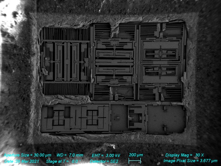
Thanks to Ryan JT Nicholl, here is the internal view of an MPU6050 IMU. The images are taken using an electron microscope after decapping the chip.
Commonly Asked Questions
Q. What is an MPU6050?
MPU6050 is an Inertial Measurement Unit or an IMU with three-axis accelerometer, three-axis gyroscope, Digital Motion Processor (DMP), and a16-bit ARC.
Q. What type of technology is used in MPU6050?
The MPU6050 is built around Micro-Electro-Mechanical technology, which is also known as MEMs.
Q. Can we tilt measure the angle with MPU6050?
Yes, we can measure the tilt angle with MPU6050.
Arduino MPU6050 Accelerometer and Gryoscope Sensor Module Interfacing Circuit Diagram
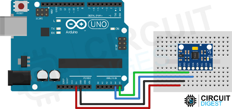
The following image shows the circuit diagram for interfacing MPU6050 with Arduino. The MPU6050 uses the I2C module for communication. Since the I2C pins are 5V tolerant, we can use them with the Arduino without any level converters. The SCL pin is connected to the SCL pin (A5) of the Arduino. Similarly, the SDA pin is connected to the SDA pin (A4) of the Arduino.
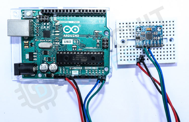
Here is how the real-life connection looks-
Arduino MPU6050 Module Code
In this example, we will read the accelerometer, gyroscope, and temperature data from the MPU6050 module and will print it to the serial monitor. For that first, we need to install the necessary libraries. For installing the libraries open the library manager in the Arduino IDE. Then search and install the following libraries: Adafruit MPU6050 library, Adafruit Unified Sensor Library, and Adafruit Bus IO Library. Once it’s done, create a new sketch and paste the code into it. Then compile and upload it to the Arduino. Once uploaded, open the serial monitor and the reading will be displayed there.
#include <Adafruit_MPU6050.h>
#include <Adafruit_Sensor.h>
#include <Wire.h>
Adafruit_MPU6050 mpu;
void setup(void) {
  Serial.begin(115200);
  // Try to initialize!
  if (!mpu.begin()) {
    Serial.println("Failed to find MPU6050 chip");
    while (1) {
      delay(10);
    }
  }
  Serial.println("MPU6050 Found!");
  // set accelerometer range to +-8G
  mpu.setAccelerometerRange(MPU6050_RANGE_8_G);
  // set gyro range to +- 500 deg/s
  mpu.setGyroRange(MPU6050_RANGE_500_DEG);
  // set filter bandwidth to 21 Hz
  mpu.setFilterBandwidth(MPU6050_BAND_21_HZ);
  delay(100);
}
void loop() {
  /* Get new sensor events with the readings */
  sensors_event_t a, g, temp;
  mpu.getEvent(&a, &g, &temp);
  /* Print out the readings */
  Serial.print("Acceleration X: ");
  Serial.print(a.acceleration.x);
  Serial.print(", Y: ");
  Serial.print(a.acceleration.y);
  Serial.print(", Z: ");
  Serial.print(a.acceleration.z);
  Serial.println(" m/s^2");
  Serial.print("Rotation X: ");
  Serial.print(g.gyro.x);
  Serial.print(", Y: ");
  Serial.print(g.gyro.y);
  Serial.print(", Z: ");
  Serial.print(g.gyro.z);
  Serial.println(" rad/s");
  Serial.print("Temperature: ");
  Serial.print(temp.temperature);
  Serial.println(" degC");
  Serial.println("");
  delay(1000);
}
Code Explanation
In the starting, we have included the Adafruit MPU6050 library, Adafruit Sensor library, and the wire library, which are necessary to communicate with the MPU6050 and get the reading. Then we have created a new instance called mpu which will be used to get the readings from the MPU6050 IMU.
#include <Adafruit_MPU6050.h>
#include <Adafruit_Sensor.h>
#include <Wire.h>
Adafruit_MPU6050 mpu;
In the setup function, we have initialized the serial communication and the MPU6050 IMU. Then the accelerometer range, gyroscope range, and filter bandwidth parameters are set. The range parameters will affect the accuracy of the reading. So, if needed these can be changed as per the library values. The setFilterBandwidth parameter will change the low pass filter bandwidth.
void setup(void) {
  Serial.begin(115200);
  // Initializethe MPU6050 IMU
  if (!mpu.begin()) {
    Serial.println("Failed to find MPU6050 chip");
    while (1) {
      delay(10);
    }
  }
  Serial.println("MPU6050 Found!");
  // set accelerometer range to +-8G
  mpu.setAccelerometerRange(MPU6050_RANGE_8_G);
  // set gyro range to +- 500 deg/s
  mpu.setGyroRange(MPU6050_RANGE_500_DEG);
  // set filter bandwidth to 21 Hz
  mpu.setFilterBandwidth(MPU6050_BAND_21_HZ);
  delay(100);
}
In the loop function, the values are read from the MPU6050 with the help of Adafruit library and then printed to the serial monitor. This will repeat every second.
void loop() {
  /* Get new sensor events with the readings */
  sensors_event_t a, g, temp;
  mpu.getEvent(&a, &g, &temp);
  /* Print out the readings */
  Serial.print("Acceleration X: ");
  Serial.print(a.acceleration.x);
  Serial.print(", Y: ");
  Serial.print(a.acceleration.y);
  Serial.print(", Z: ");
  Serial.print(a.acceleration.z);
  Serial.println(" m/s^2");
  Serial.print("Rotation X: ");
  Serial.print(g.gyro.x);
  Serial.print(", Y: ");
  Serial.print(g.gyro.y);
  Serial.print(", Z: ");
  Serial.print(g.gyro.z);
  Serial.println(" rad/s");
  Serial.print("Temperature: ");
  Serial.print(temp.temperature);
  Serial.println(" degC");
  Serial.println("");
  delay(1000);
}
MPU6050 Interfacing with Arduino
The below GIF shows how we can interface an MPU6050 with the Arduino. You can see that when the module is rotated the value changes depends on the axis of rotation.
Projects Using MPU6050 IMU
There are some interesting projects done with the MPU6050 IMU. If you want to know more about those topics, links are given below.
Robotic Arms are one of the fascinating engineering creations and this 3D printed robotic arm position is controlled through a hand glove that is attached with an MPU6050 Gyroscope and a flex sensor.
In this tutorial I will document my experience in building the self balancing robot. You will get to know how to make self balancing robot. We provided circuit, code, and a step-by-step guide
In this tutorial, we are going to build an easy and cheap Pedometer using ATtiny85 IC, MPU6050 Accelerometer & Gyroscope, and OLED Display Module. This simple Arduino based step counter is powered by a 3V coin cell, making it easy to carry when you go out for a walk or jog.
Supporting Files
Complete Project Code
#include <Adafruit_MPU6050.h>
#include <Adafruit_Sensor.h>
#include <Wire.h>
Adafruit_MPU6050 mpu;
void setup(void) {
  Serial.begin(115200);
  // Try to initialize!
  if (!mpu.begin()) {
    Serial.println("Failed to find MPU6050 chip");
    while (1) {
      delay(10);
    }
  }
  Serial.println("MPU6050 Found!");
  // set accelerometer range to +-8G
  mpu.setAccelerometerRange(MPU6050_RANGE_8_G);
  // set gyro range to +- 500 deg/s
  mpu.setGyroRange(MPU6050_RANGE_500_DEG);
  // set filter bandwidth to 21 Hz
  mpu.setFilterBandwidth(MPU6050_BAND_21_HZ);
  delay(100);
}
void loop() {
  /* Get new sensor events with the readings */
  sensors_event_t a, g, temp;
  mpu.getEvent(&a, &g, &temp);
  /* Print out the readings */
  Serial.print("Acceleration X: ");
  Serial.print(a.acceleration.x);
  Serial.print(", Y: ");
  Serial.print(a.acceleration.y);
  Serial.print(", Z: ");
  Serial.print(a.acceleration.z);
  Serial.println(" m/s^2");
  Serial.print("Rotation X: ");
  Serial.print(g.gyro.x);
  Serial.print(", Y: ");
  Serial.print(g.gyro.y);
  Serial.print(", Z: ");
  Serial.print(g.gyro.z);
  Serial.println(" rad/s");
  Serial.print("Temperature: ");
  Serial.print(temp.temperature);
  Serial.println(" degC");
  Serial.println("");
  delay(500);
}

