If you're looking to add wireless communication to your project, the Arduino nRF24L01 module combo is one of the most reliable and cost-effective solutions available. Whether you're building a DIY spy bug, a long-range walkie-talkie, or just want to control stuff wirelessly, the Arduino nRF24L01 setup gives you the flexibility to send and receive data wirelessly over long distances using the 2.4GHz band.
In this article, we’ll walk you through everything you need to know to get started with Arduino and nRF24L01 modules. From wiring diagrams and library installation to example codes and troubleshooting tips, we’ll cover it all. By the end, you'll have a solid foundation to build your own wireless Arduino projects using the powerful nRF24L01 transceiver module.
Table of Contents
Before we get started it is important to understand that there two types of nRF24L01 modules available in the market one is called just nRF24L01 and the other is called nRF24L01+ PA+LN. While both the modules have the same pinout and work the same the nRF24L01+ PA+LN modules come with an antenna and claim to have a longer range. In this article, we have used the simple nRF24L01 module on the transmitter side and the nRF24L01+PA+LN module on the receiver side so that its easy for you to understand the working of both the modules. Also this article is limited only to sending data between two Arduino boards and nRF24L01 module, but you can also use the nRF24L01 module to send data wirelessly between Arduino and Raspberry Pi and use nRF24L01 as a BLE module to communicate between Arduino and smartphones.
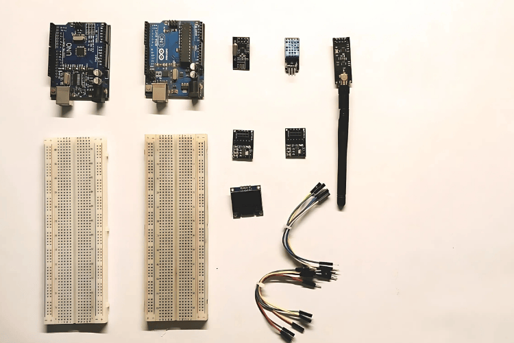
Components Required
1. Arduino Uno – x2
2. nRF24L01 – x2
3. 3.3V Adapter Board for nRF24L01 Wireless Module – x2
4. DHT11
5. OLED display
6. Jumper wires
7. Breadboard – x2
Overview of nRF24L01 Module
The nRF24L01 is a small, low-price Wi-Fi verbal exchange module that keeps records over short distances. It uses radio waves to switch information at 2.4GHz, just like Wi-Fi however with decreased electricity intake. The operating voltage is 3.3V. Don’t exceed this voltage limit.
nRF24L01 uses just 12mA current during transmission, which is quite low compared to some LEDs. It only utilizes 26µA current in standby mode and 900nA in power-down mode.
This module is generally used with microcontrollers like Arduino to create wireless connections between devices. It allows a range of as long as a hundred meters in open areas. This module can cover 100 meters if used effectively and it can also cover 1000 meters if you use it with an antenna.
The nRF24L01 is very suitable for projects like remote controls, home automation, and wireless sensors. It’s easy to use, because of its SPI interface, which allows it to communicate quickly with the Arduino. The module is lightweight, energy-efficient, and can work reliably with minimal interference, making it ideal for beginners and advanced users who want to explore wireless data transfer. People commonly use it to make a drone or an RC car.
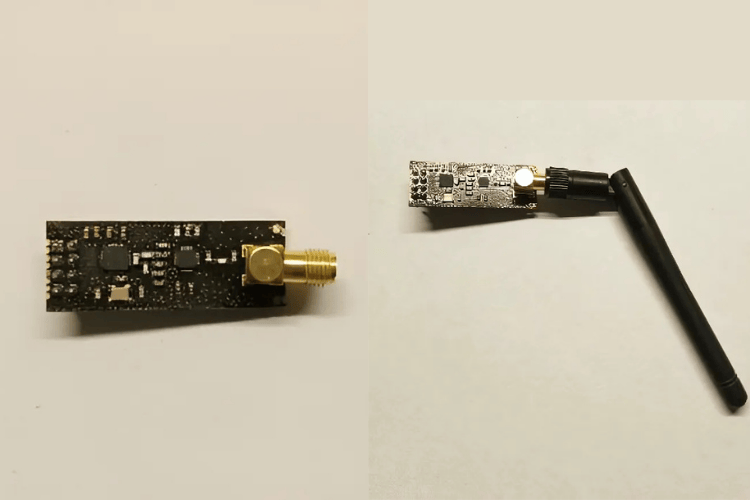
nRF24L01 PA LNA Wireless Transceiver Module with External Antenna
This nRF24L01 module is the same as the one shown above but the main difference is that it has an antenna for an extended-range facility.
It includes an RFX2401C range extender chip that combines PA, LNA, and transmit-receive switching circuitry. Because of this onboard chip, we get a higher range of approximately 1000+ meters.
PA stands for Power Amplifier, and LNA stands for Low-Noise Amplifier. The PA amplifies the weak signals transmitted by the nRF24L01 chip, while the LNA amplifies an extremely weak signal received from the antenna.
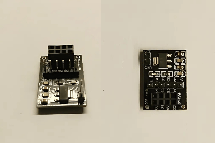
3.3V Adapter Board for nRF24L01
This is a 3.3V adaptor Board for the nRF24L01 module. As you can see the pins of nRF24L01 are not compatible with the breadboard but now with this adapter board we can easily connect the nRF24L01 pins to Arduino.
The nRF24L01 module works properly on 3.3V, so this adapter module can provide a steady and smooth 3.3V for it to function properly. The adapter can take up to 15V input, but we recommend staying below 12V.
Technical Specifications of nRF24L01
How Does The nRF24L01+ Module Work?
Only at a specific frequency, nRF24L01 works and that is called a channel. If we want two or more modules to exchange data between them then we must put them on the same channel which means between 2.400 and 2.525 GHz frequency.
This means we have 125 different possible channels, each taking up to 1MHz of bandwidth. This is one of the best features of the NRF24L01 module, as it provides 125 different channels to operate upon.
There is a gap of 1MHz between the two channels, which is required to transmit data over air between 250kbps and 1Mbps. Doing this doesn't cause problems, but what if we want to transfer 2Mbps data over air? So, to transfer 2Mbps data over the air, we need a 2MHz gap between the two channels. This ensures non-overlapping channels and establishes smooth communication between both parties.
nRF24L01 Module Pinouts
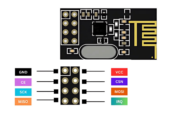
GND – It should be connected to the ground of the power source.
VCC - It supplies power to the module. The power input range should be between 1.9 volts and 3.9 volts but for your information it works best at 3.3V. You can connect it directly to the 3.3V output of your Arduino board. Make sure you don't supply more than 4 volts, you gonna kill it.
CE (Chip Enable)—This pin is usually an active-high pin. Depending on its mode, the NRF24L01 will either transmit or receive data over the air.
CSN (Chip Select Not) - This is an active-low pin that is held high. The NRF24L01 can only listen to data on its SPI port when this pin goes low.
SCK (Serial Clock) - When the SPI bus master sends the clock pulses then this pin comes into play to accept those clock pulses.
MOSI (Master Out Slave In) - This pin is the SPI input to the module. Through this pin module receives the data from the microcontroller.
MISO (Master In Slave Out) - This pin is the SPI output from the module. Through this pin, the module sends the data to the microcontroller.
IRQ - This is an interrupt pin and the job of this pin is to alert the master when the new data is available to process.
Wiring nRF24L01 with Arduino Uno
Now, we know many things about NRF24LO1 and its workings. So, let's start making a project with it and learn more about it.
Now, we gonna start first with GND and VCC. Connect the GND and VCC pin of this module to the GND and VCC of Arduino Uno.
Let's connect the SPI pins. Keep in mind that SPI pins are different in different versions of Arduino. In Our board which is Arduino Uno, the SPI pins are 13 (SCK), 12 (MISO), 11 (MOSI), AND 10 (SS).
Keep in mind that for both the transmitter and receiver the connections with the Arduino are the same.
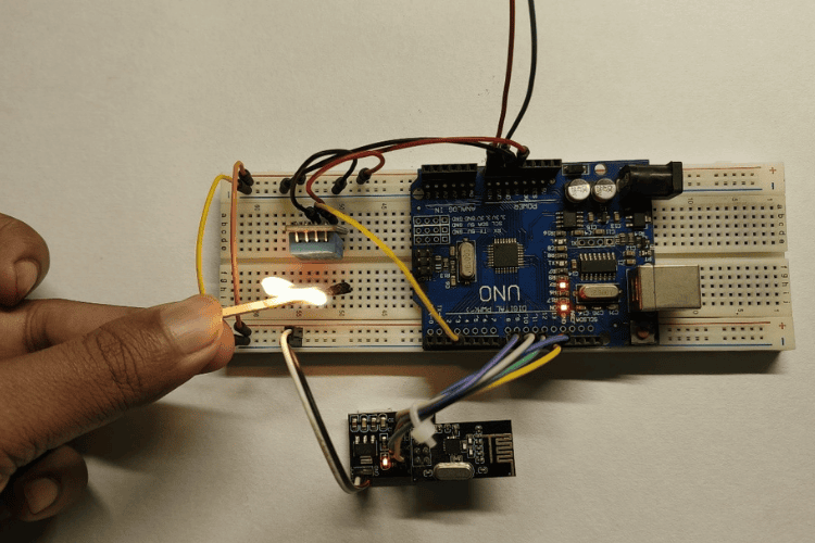
Arduino Uno Connection with nRF24L01 as Transmitter
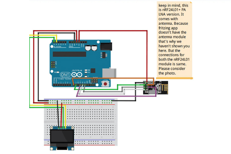
You can also make connections with the help of the image given below. Connect the data pin of the DHT11 sensor to the digital PIN 3 of Arduino.

Connect the GND and VCC of the OLED to the GND and VCC of the Arduino, and connect SCK/SCL and SDA to the A5 and A4 of the Arduino.
Arduino Uno Connection with nRF24L01 as Receiver
Code for Arduino Uno With nRF24L01 As Transmitter
To make our code function properly first, we need to add some libraries. The libraries are SPI.h, nRF24L01.h, RF24.h, DHT.h. To download these libraries you need to follow these instructions.
Click on Sketch > Include Library > Manage Libraries and now search in the search bar the names of the libraries that I have mentioned above then install them one by one.
#include <SPI.h>
#include <nRF24L01.h>
#include <RF24.h>
#include <DHT.h>
#define DHTPIN 4     // DHT11 data pin
#define DHTTYPE DHT11
RF24 radio(9, 8);   // CE, CSN pins for nRF24L01
const byte address[6] = "00001";
DHT dht(DHTPIN, DHTTYPE);
struct SensorData {
 float temperature;
 float humidity;
};
void setup() {
 Serial.begin(9600);
 dht.begin();
 radio.begin();
 radio.openWritingPipe(address);
 radio.setPALevel(RF24_PA_LOW);
 radio.stopListening();
}
void loop() {
 SensorData data;
 data.temperature = dht.readTemperature();
 data.humidity = dht.readHumidity();
 if (isnan(data.temperature) || isnan(data.humidity)) {
   Serial.println("Failed to read from DHT sensor!");
   return;
 }
 bool success = radio.write(&data, sizeof(data));
 if (success) {
   Serial.println("Data sent successfully!");
 } else {
   Serial.println("Data send failed.");
 }
 delay(2000); // Send data every 2 seconds
}
nRF24L01 Code Explanation as Transmitter
SPI.h, nRF24L01.h, and RF24.h: We need these libraries to communicate with the NRF24L01 module. DHT.H : This library is required to read the data from the DHT11 sensor.
Pin Definitions
#include <SPI.h>
#include <nRF24L01.h>
#include <RF24.h>
#include <DHT.h>
#define DHTPIN 4     // DHT11 data pin
#define DHTTYPE DHT11
RF24 radio(9, 8);   // CE, CSN pins for nRF24L01
const byte address[6] = "00001";
DHT dht(DHTPIN, DHTTYPE);
struct SensorData {
 float temperature;
 float humidity;
};
So, what we are trying to do here is that we have included some libraries, declared some variables, created an object “dht” and “radio” and created a structure called “sensorData” which holds temperature and humidity.
address[6] = "00001": The address ensures the radio module sends data to the correct receiver.
dht.begin(), radio.begin(): Here, we are initializing the nRF24L01 radio module and DHT11 sensor.
radio.setPALevel(RF24_PA_LOW): sets the radio module's power level to low.
Send data by opening the communication pipe (openWritingPipe(address)) and turning off receiving mode (stopListening()).
SensorData data;
 data.temperature = dht.readTemperature();
 data.humidity = dht.readHumidity();
 if (isnan(data.temperature) || isnan(data.humidity)) {
   Serial.println("Failed to read from DHT sensor!");
   return;
 }
 bool success = radio.write(&data, sizeof(data));
 if (success) {
   Serial.println("Data sent successfully!");
 } else {
   Serial.println("Data send failed.");
 }
 delay(2000); // Send data every 2 seconds
The loop() function repeatedly reads temperature and humidity data from the DHT11 sensor, checks for valid readings, and sends the data wirelessly using the nRF24L01 module. If the sensor readings are invalid, it logs an error message and skips transmission for that cycle.
For valid readings, it attempts to transmit the data and logs whether the transmission was successful or not. The function waits for 2 seconds before starting the process again, ensuring periodic updates.
Code for Arduino Uno with nRF24L01 As Receiver
Now, as you have already installed some of the libraries given above, this time you need to install two more libraries to make the code function properly. These two libraries help OLED display to work properly. Without these libraries, your OLED display would not work. The libraries are Adafruit_GFX.h, Adafruit_SSD1306.h. Their installation procedure is the same as mentioned above.
#include <SPI.h>
#include <nRF24L01.h>
#include <RF24.h>
#include <Adafruit_GFX.h>
#include <Adafruit_SSD1306.h>
#define SCREEN_WIDTH 128
#define SCREEN_HEIGHT 64
RF24 radio(9, 8);   // CE, CSN pins for nRF24L01
const byte address[6] = "00001";
Adafruit_SSD1306 display(SCREEN_WIDTH, SCREEN_HEIGHT, &Wire, -1);
struct SensorData {
 float temperature;
 float humidity;
};
void setup() {
 Serial.begin(9600);
 // Initialize OLED display
 if (!display.begin(SSD1306_SWITCHCAPVCC, 0x3C)) {
   Serial.println("SSD1306 allocation failed");
   for (;;);
 }
 display.clearDisplay();
 display.setTextSize(1);
 display.setTextColor(SSD1306_WHITE);
 // Initialize nRF24L01
 radio.begin();
 radio.openReadingPipe(1, address);
 radio.setPALevel(RF24_PA_LOW);
 radio.startListening();
}
void loop() {
 if (radio.available()) {
   SensorData data;
   radio.read(&data, sizeof(data));
   // Display data on OLED
   display.clearDisplay();
   display.setTextSize(2);
   display.setCursor(0, 0);
   display.println("Data:");
   display.setTextSize(1);
   display.setCursor(0, 30);
   display.print("Temp: ");
   display.setCursor(60, 30);
   display.print(data.temperature);
   display.println(" C");
   display.setCursor(0, 45);
   display.print("Humidity: ");
   display.print(data.humidity);
   display.println(" %");
   display.display();

   Serial.println("Data received:");
   Serial.print("Temp: ");
   Serial.print(data.temperature);
   Serial.println(" C");
   Serial.print("Humidity: ");
   Serial.print(data.humidity);
   Serial.println(" %");
 }
 delay(1000);
}
nRF24L01 Code Explanation as Receiver
OLED Display Settings
Adafruit_SSD1306 display(SCREEN_WIDTH, SCREEN_HEIGHT, &Wire, -1);
struct SensorData {
  float temperature;
  float humidity;
};
The OLED display resolution is defined as 128x64 pixels (SCREEN_WIDTH and SCREEN_HEIGHT).
Adafruit_SSD1306 display: Sets up the OLED display.
SensorData: A structure to hold the received temperature and humidity values.
void setup() {
 Serial.begin(9600);
 // Initialize OLED display
 if (!display.begin(SSD1306_SWITCHCAPVCC, 0x3C)) {
   Serial.println("SSD1306 allocation failed");
   for (;;);
 }
 display.clearDisplay();
 display.setTextSize(1);
 display.setTextColor(SSD1306_WHITE);
 // Initialize nRF24L01
 radio.begin();
 radio.openReadingPipe(1, address);
 radio.setPALevel(RF24_PA_LOW);
 radio.startListening();
}
The setup() function initializes the OLED display and the nRF24L01 module for wireless communication. It sets up the serial monitor for debugging, prepares the OLED screen for use, and configures the nRF24L01 to operate as a receiver by opening a reading pipe and starting listening mode. If the OLED initialization fails, it halts the program and logs an error.
void loop() {
 if (radio.available()) {
   SensorData data;
   radio.read(&data, sizeof(data));
   // Display data on OLED
   display.clearDisplay();
   display.setTextSize(2);
   display.setCursor(0, 0);
   display.println("Data:");
   display.setTextSize(1);
   display.setCursor(0, 30);
   display.print("Temp: ");
   display.setCursor(60, 30);
   display.print(data.temperature);
   display.println(" C");
   display.setCursor(0, 45);
   display.print("Humidity: ");
   display.print(data.humidity);
   display.println(" %");
   display.display();

   Serial.println("Data received:");
   Serial.print("Temp: ");
   Serial.print(data.temperature);
   Serial.println(" C");
   Serial.print("Humidity: ");
   Serial.print(data.humidity);
   Serial.println(" %");
 }
 delay(1000);
}
The loop() function constantly checks if new data has been received from the nRF24L01 module. If data is available, it reads the temperature and humidity values and displays them on the OLED screen with clear formatting. It also prints the same data to the serial monitor for debugging. After showing the data, the program waits for one second before checking for new data again.
Working of nRF24L01 Using Arduino
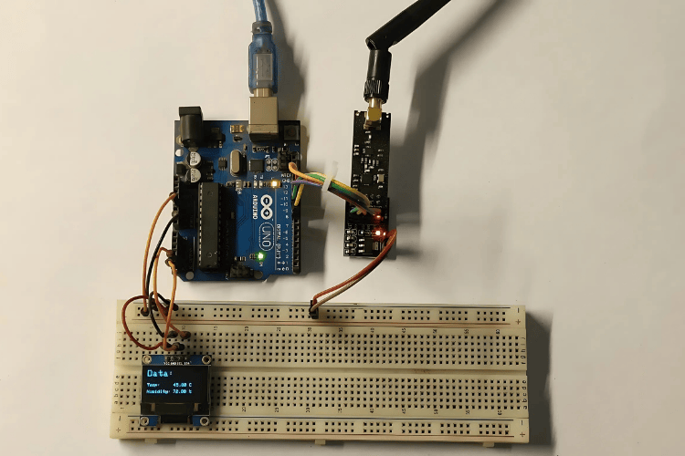
So, here we tried to make a portable wireless weather station, it is not very fancy or extremely accurate but still, it gives you a good idea of how nRF24L01 works and how can we use it to make anything wireless.
The first code reads temperature and humidity data from a DHT11 sensor and sends it wirelessly using an nRF24L01 module.
The second code receives this data using another nRF24L01 module and displays it on an OLED screen while printing it to the serial monitor for debugging.
Together, these codes create a simple wireless monitoring system where one device collects environmental data and sends it to another device for display and logging.
In this article, you read about the nRF24L01 module and how to interface it with the Arduino. You also learned about “How does it work?” and this module is available for very cheap in online markets. It’s a potent module and depends on how you use it. You can make many incredible and unimaginable things with it. It gives a new direction to your imagination. So, try this and learn more.
Keep Learning and Keep Hustling.
Similar nRF24L01 and Arduino Wireless Projects
Here are some related projects that involve wireless communication using nRF24L01 and Arduino
")
Sending Sensor Data to Android Phone using Arduino and NRF24L01 over Bluetooth (BLE)
Transmit sensor data from Arduino to an Android phone using nRF24L01 modules over BLE.

Wireless Controlled Shutter Button for DSLR using Arduino and nRF24L01
Control your DSLR camera's shutter wirelessly using Arduino and nRF24L01 modules.

Create a Private Chat Room using Arduino, nRF24L01 and Processing
Learn to Set up a local chat room using Arduino and nRF24L01 modules for wireless text communication.

Wireless RF Communication using nRF24L01 Module
Establish wireless communication between Arduino and Raspberry Pi using nRF24L01 modules.

Interfacing nRF24L01 with Arduino: Controlling Servo Motor
Learn how to control a servo motor wirelessly using Arduino and nRF24L01 modules.

Arduino based Audio Spy Bug using NRF24L01
Create a wireless audio surveillance system using Arduino and nRF24L01 modules.

Long Range Arduino Based Walkie Talkie using nRF24L01
Build a walkie-talkie system using Arduino and nRF24L01 modules for long-range communication.