Welcome to our blog post on interfacing the WS2811 (5V) RGB LED strip with Arduino! In this guide, we will walk you through the process of connecting and controlling WS2811 LED strips using an Arduino microcontroller. WS2811 LED strips are popular due to their individually addressable RGB LEDs, allowing for captivating lighting effects in various projects, including home decor, art installations, and DIY electronics. Here is the previous project where we build a fun project LED Arcade Game using WS2811 RGB LED strip.
In this blog post, we will cover the essential steps involved in setting up the hardware and software for your WS2811 LED strip. We'll explain the necessary connections between the LED strip, Arduino board, and power supply, along with the software libraries required to control the LEDs. Additionally, we will provide sample code snippets and explanations to help you get started quickly.
Hardware Setup
RGB LED stands for Red, Green, and Blue Light-Emitting Diode. It is a type of LED that contains three individual LEDs in a single package, with each LED capable of emitting red, green, or blue light independently. By combining different intensities of these primary colors, an RGB LED can produce a wide range of colors, including a full spectrum of hues.
RGB LED Pinout
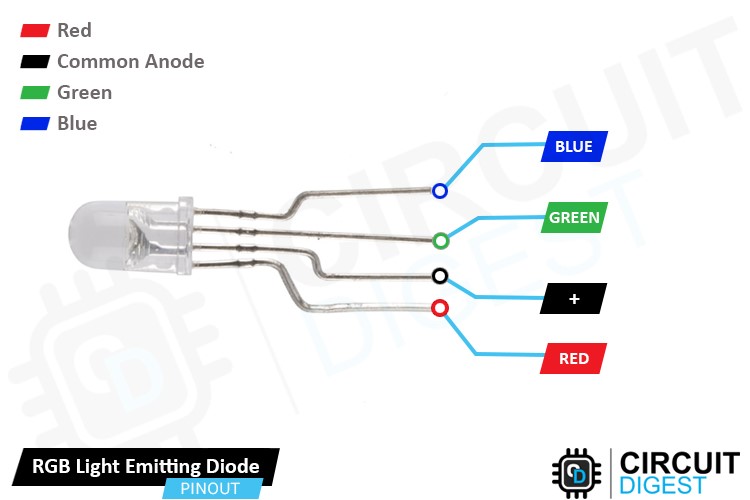
Anode Connection: The longest pin of the common anode RGB LED is the anode (+) pin. It is connected to a positive voltage supply, typically 5V. This anode pin is shared among all three color LEDs.
Cathode Connection: There are three shorter pins, each representing the cathode (-) connection of the individual color LEDs (red, green, and blue). These cathode pins are independent and not connected to each other.
Types of RGB LED
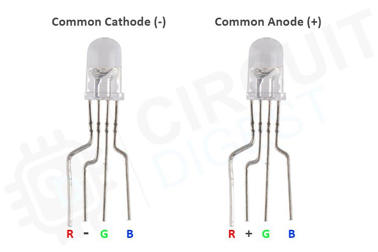
There are three main types of RGB leds
Common Anode RGB LED: In this type, the anode (+) terminal of the red, green, and blue LEDs is connected together and shared as the common pin. Each cathode (-) terminal of the individual LEDs is connected to a separate pin. To light up a specific color, the common pin is connected to a positive voltage, and the desired LED cathodes are connected to ground (GND) through appropriate resistors.
Common Cathode RGB LED: In this type, the cathode (-) terminal of the red, green, and blue LEDs is connected together and shared as the common pin. Each anode (+) terminal of the individual LEDs is connected to a separate pin. To light up a specific color, the common pin is connected to ground (GND), and the desired LED anodes are connected to a positive voltage through appropriate resistors.
Addressable RGB LED: Also known as individually addressable or digital RGB LED, this type incorporates built-in ICs (Integrated Circuits) within each LED package. These ICs allow each LED to be controlled independently, making it possible to create complex lighting effects and patterns. Addressable RGB LEDs are typically controlled via a data line, such as the WS2811, WS2812, or APA102 protocols.
RGB LED Working
Controlling Colors: To light up a specific color, you need to create a current path from the common anode (+) to the desired cathode pins (R, G, B). By connecting the cathode pins to the ground (GND) through appropriate current-limiting resistors, you can control the intensity of each color LED.
To turn on the red LED, you would connect the cathode of the red LED (R) to ground (GND) by activating the corresponding GPIO pin of your microcontroller or Arduino.
Similarly, you can control the green LED (G) and blue LED (B) by connecting their respective cathode pins to ground (GND) through GPIO pins.
Color Mixing: By adjusting the intensity of each color LED, you can create different color combinations. Varying the current flowing through each cathode pin allows you to mix different levels of red, green, and blue light, resulting in a wide range of colors.
For example, if you want to create a purple color, you would activate the red (R) and blue (B) LEDs by connecting their cathodes to ground (GND) while keeping the green (G) LED inactive.
By controlling the on/off state and intensity of each cathode connection, you can achieve different colors, including white (all three LEDs on), different shades of red, green, blue, and various combinations in between.
WS2811 LED Driver Pinout
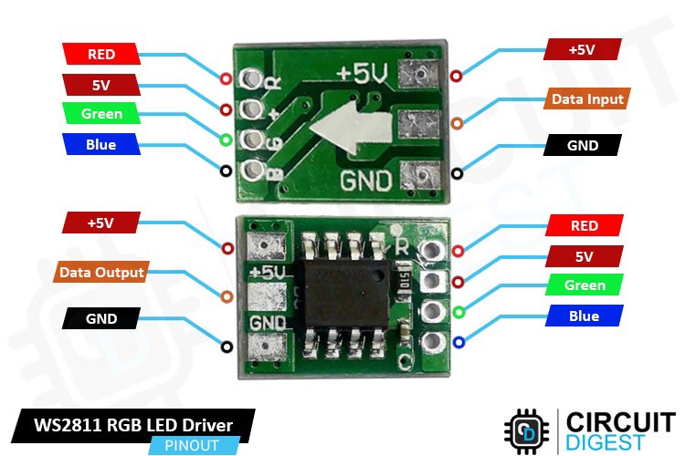
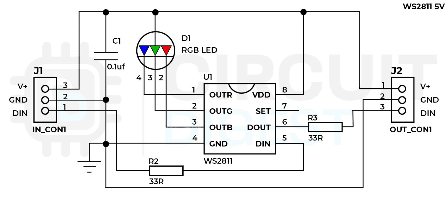
GND This pin connects to the ground (GND) or 0V reference of the power supply.
DATA This pin is the data input for the WS2811 driver. It receives the control data from the microcontroller or Arduino, usually through a digital output pin.
VCC This pin connects to the positive supply voltage (VCC) of the power source. The WS2811 typically operates at 5V, so this pin is usually connected to the +5V power supply.
R-OUT This pin is the output for the red color channel of the addressable RGB LED. It is connected to the anode (+) of the red LED within the RGB LED package.
G-OUT This pin is the output for the green color channel of the addressable RGB LED. It is connected to the anode (+) of the green LED within the RGB LED package.
B-OUT This pin is the output for the blue color channel of the addressable RGB LED. It is connected to the anode (+) of the blue LED within the RGB LED package.
DOUT This pin is the data output for daisy-chaining multiple WS2811 ICs. It allows the control data to be passed on to the next WS2811 IC in the chain.
Circuit Diagram of WS2811 Driver
In this circuit, a 5V power supply is used to provide a constant current output of approximately 18.5mA per output pin of the WS2811 driver. This ensures consistent luminescence and color temperature of the RGB LED. A 104 (0.1µF) non-polarized capacitor acts as a bypass capacitor to filter AC components in the power rail. Two optional 33-ohm resistors match impedance at the data port. The circuit shows a common anode RGB LED configuration.
Working of WS2811 LED Driver
The WS2811 driver receives data in a specific format that represents the desired color and intensity for each LED. The control data is sent serially, and each LED along the chain interprets its respective data segment to determine its color output.
Each bit of data sent to the WS2811 driver consists of a high or low signal level that represents the color intensity for a specific LED. The timing of these high and low levels is critical. The WS2811 uses specific durations to differentiate between a "0" and a "1" bit. For example, a short high pulse followed by a long low pulse might represent a "0" bit, while a long high pulse followed by a short low pulse might represent a "1" bit.
The WS2811 driver expects data to be transmitted in frames, where each frame consists of a series of bits representing the desired colors for all the connected LEDs. The timing between frames is important to separate one frame from the next and ensure proper synchronization. Typically, a short low signal is used to indicate the end of one frame and the beginning of the next.
The WS2811 driver requires a reset pulse to initialize the data reception process. This reset pulse should have a duration longer than 50µs to ensure the WS2811 IC is in the proper state to start receiving the data.
The timing requirements of the WS2811 driver are quite stringent, and the signal timings need to be within specific tolerances for reliable operation. Timing deviations beyond these tolerances can lead to data corruption and inaccurate color representation.
Color Mixing: The WS2811 driver controls RGB (red, green, blue) addressable LEDs. To achieve different colors, it varies the intensity of each color channel by adjusting the duty cycle of the PWM signal. By combining different levels of red, green, and blue, the driver can create a wide range of colors. For example, mixing full intensity of red and green results in yellow, while mixing full intensity of red and blue produces magenta.
PWM Control: PWM is a technique that modulates the width of pulses in a digital signal to control the average power or intensity of a corresponding output. The WS2811 driver uses PWM to control the brightness of each LED. It rapidly turns the LED on and off at a specific frequency, adjusting the duration of the "on" state (duty cycle) to control the perceived brightness. By varying the duty cycle of the PWM signal for each color channel, the WS2811 driver can create different levels of intensity for red, green, and blue, allowing for precise color control.
Parts of WS2811 LED
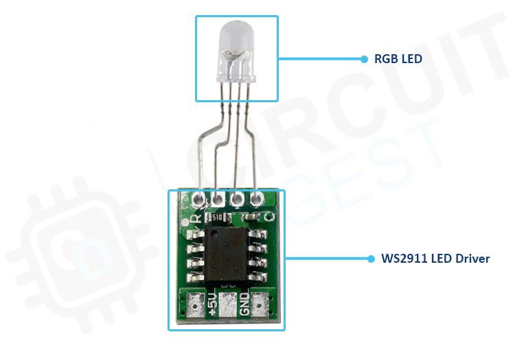
The basic circuit for WS2811 consists of the following components:
- WS2811 IC: The WS2811 chip itself is the heart of the circuit. It integrates the control circuitry and drive circuitry required to control the RGB LEDs.
- RGB LEDs: The WS2811 is designed to control RGB LEDs, which contain three separate LED elements: one for red, one for green, and one for blue. Each LED can be independently controlled to produce a wide range of colors.
The WS2811 ICs are daisy-chained, meaning the data output of one IC connects to the data input of the next IC, allowing for control of multiple LEDs in a sequential manner.
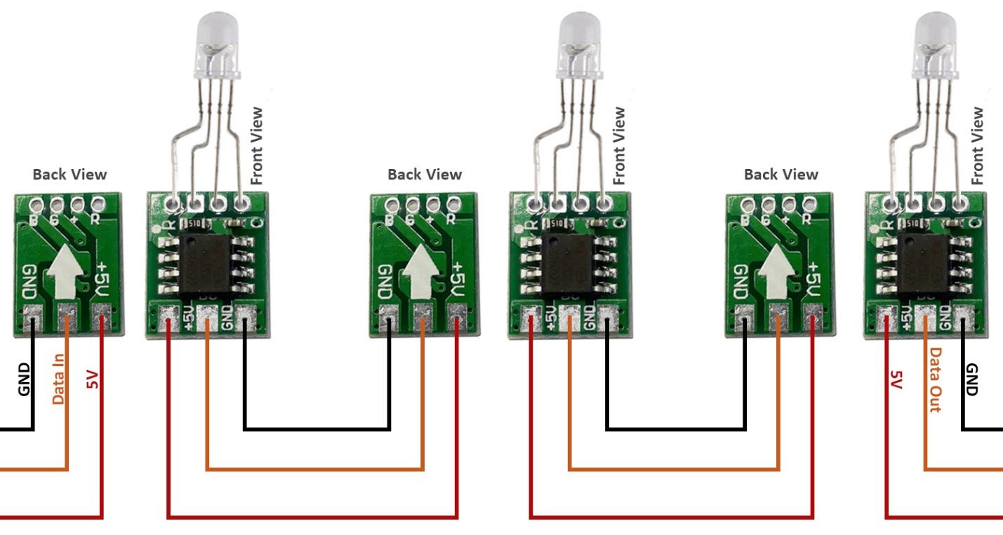
WS2811 LED Strip Pinout
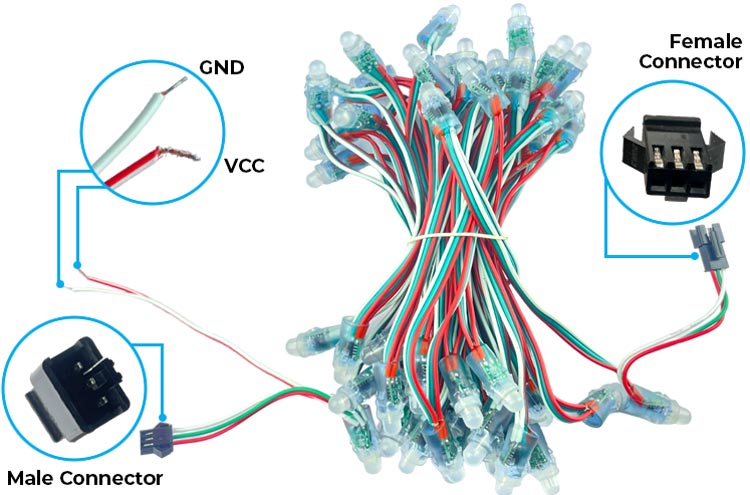
As you can see in the image, there is a male end and a female end. The female end can be connected to another male end, thus elongating the wire.
As much as you would like to elongate the wires to infinity by using only the Arduino, the Arduino’s voltage regulator will only allow max current up to 1A. So, we suggest to use an external 5V power supply.
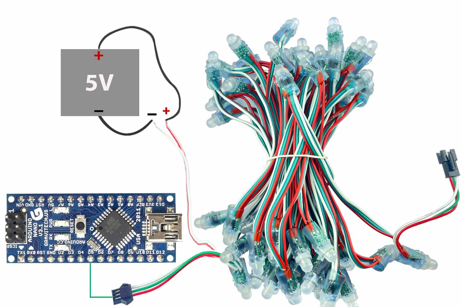
Circuit Diagram of Interfacing Arduino with WS2811 LED Strip
Connect the 5V power supply's positive terminal to the +5V pin of the WS2811 LED strip.
Connect the 5V power supply's negative terminal to the GND pin of the LED strip.
Connect the data pin of the LED strip to the digital pin 5 on the Arduino. Note the pin number for later use.
Software Setup
Open the Arduino IDE and Install the FastLED library in the Arduino IDE (Sketch -> Include Library -> Manage Libraries -> Search for "FastLED" -> Install).

Copy Paste any Code from the ones given below and upload it on the Arduino Nano.
Code Implementation for all 5 patterns
Code for Pattern 1:
#include <FastLED.h>
#define LED_PIN 5    // Replace with the pin number you used for DATA connection
#define NUM_LEDS 50  // Replace with the number of LEDs in your strip
#define DELAY_TIME 20  // Delay between LED movements (in milliseconds)
CRGB leds[NUM_LEDS];
void setup() {
  FastLED.addLeds<WS2811, LED_PIN, RGB>(leds, NUM_LEDS);
}
void loop() {
  // Turn off all LEDs
  for (int i = 0; i < NUM_LEDS; i++) {
    leds[i] = CRGB::Black;
  }
  // Move the LED chaser
  for (int i = 0; i < NUM_LEDS; i++) {
    leds[i] = CRGB::Blue;  // Set the current LED to blue
    FastLED.show();  // Update the LED strip
    delay(DELAY_TIME);  // Delay between LED movements
  }
  // Move the LED chaser in reverse
  for (int i = NUM_LEDS - 1; i >= 0; i--) {
    leds[i] = CRGB::Green;  // Set the current LED to green
    FastLED.show();  // Update the LED strip
    delay(DELAY_TIME);  // Delay between LED movements
  }
}
Code for Pattern 2:
#include <FastLED.h>
#define LED_PIN 5    // Replace with the pin number you used for DATA connection
#define NUM_LEDS 50  // Replace with the number of LEDs in your strip
#define DELAY_TIME 50  // Delay between color changes (in milliseconds)
CRGB leds[NUM_LEDS];
void setup() {
  FastLED.addLeds<WS2811, LED_PIN, RGB>(leds, NUM_LEDS);
}
void loop() {
  static uint8_t hue = 0;  // Hue value for color shifting
  // Set all LEDs to the current hue
  for (int i = 0; i < NUM_LEDS; i++) {
    leds[i] = CHSV(hue, 255, 255);
  }
  FastLED.show();  // Update the LED strip
  delay(DELAY_TIME);  // Delay between color changes
  // Shift the hue for the next frame
  hue++;
}
Code for Pattern 3:
#include <FastLED.h>
#define LED_PIN 5       // Replace with the pin number you used for DATA connection
#define NUM_LEDS 50      // Replace with the number of LEDs in your strip
#define FADE_DELAY 1   // Delay between brightness changes (in milliseconds)
#define MAX_BRIGHTNESS 255 // Maximum brightness value
CRGB leds[NUM_LEDS];
void setup() {
  FastLED.addLeds<WS2811, LED_PIN, RGB>(leds, NUM_LEDS);
}
void loop() {
  // Increase brightness
  for (int brightness = 0; brightness <= MAX_BRIGHTNESS; brightness++) {
    setBrightness(brightness);
    delay(FADE_DELAY);
  }
  // Decrease brightness
  for (int brightness = MAX_BRIGHTNESS; brightness >= 0; brightness--) {
    setBrightness(brightness);
    delay(FADE_DELAY);
  }
}
void setBrightness(int brightness) {
  for (int i = 0; i < NUM_LEDS; i++) {
    leds[i] = CRGB(brightness, brightness, brightness);
  }
  FastLED.show();  // Update the LED strip
}
Code for Pattern 4:
#include <FastLED.h>
#define LED_PIN 5        // Replace with the pin number you used for DATA connection
#define NUM_LEDS 50       // Replace with the number of LEDs in your strip
#define GRADIENT_DELAY 50 // Delay between gradient color changes (in milliseconds)
#define MOVEMENT_DELAY 20 // Delay between LED movements (in milliseconds)
CRGB leds[NUM_LEDS];
void setup() {
  FastLED.addLeds<WS2811, LED_PIN, RGB>(leds, NUM_LEDS);
}
void loop() {
  // Set the initial color gradient
  CRGB startColor = CRGB::Red;
  CRGB endColor = CRGB::Blue;
  // Calculate color step values
  int colorStepsR = (endColor.r - startColor.r) / NUM_LEDS;
  int colorStepsG = (endColor.g - startColor.g) / NUM_LEDS;
  int colorStepsB = (endColor.b - startColor.b) / NUM_LEDS;
  // Move the gradient effect across the LED strip
  for (int i = 0; i < NUM_LEDS; i++) {
    CRGB gradientColor = CRGB(startColor.r + (colorStepsR * i),
                             startColor.g + (colorStepsG * i),
                             startColor.b + (colorStepsB * i));
    // Shift the gradient by moving the LEDs
    for (int j = 0; j < NUM_LEDS; j++) {
      int index = (i + j) % NUM_LEDS;
      leds[index] = gradientColor;
    }
    FastLED.show();  // Update the LED strip
    delay(MOVEMENT_DELAY);  // Delay between LED movements
  }
  // Shift the colors for the next frame
  startColor = endColor;
  endColor = CRGB::Green;
}
Code for Pattern 5:
#include <FastLED.h>
#define LED_PIN 5         // Replace with the pin number you used for DATA connection
#define NUM_LEDS 50       // Replace with the number of LEDs in your strip
#define FLICKER_DELAY 20  // Delay between flicker changes (in milliseconds)
CRGB leds[NUM_LEDS];
void setup() {
  FastLED.addLeds<WS2811, LED_PIN, RGB>(leds, NUM_LEDS);
}
void loop() {
  // Set the initial color for the candle flame
  CRGB flameColor = CRGB::Red;
  // Create a flickering effect
  for (int i = 0; i < NUM_LEDS; i++) {
    // Randomly flicker the LEDs
    if (random(10) < 5) {
      leds[i] = flameColor;
    } else {
      leds[i] = CRGB::Black;
    }
  }
  FastLED.show();  // Update the LED strip
  delay(FLICKER_DELAY);  // Delay between flicker changes
}
Complete Project Code
Code for Pattern 1:
#include <FastLED.h>
#define LED_PIN 5    // Replace with the pin number you used for DATA connection
#define NUM_LEDS 50  // Replace with the number of LEDs in your strip
#define DELAY_TIME 20  // Delay between LED movements (in milliseconds)
CRGB leds[NUM_LEDS];
void setup() {
  FastLED.addLeds<WS2811, LED_PIN, RGB>(leds, NUM_LEDS);
}
void loop() {
  // Turn off all LEDs
  for (int i = 0; i < NUM_LEDS; i++) {
    leds[i] = CRGB::Black;
  }
  // Move the LED chaser
  for (int i = 0; i < NUM_LEDS; i++) {
    leds[i] = CRGB::Blue;  // Set the current LED to blue
    FastLED.show();  // Update the LED strip
    delay(DELAY_TIME);  // Delay between LED movements
  }
  // Move the LED chaser in reverse
  for (int i = NUM_LEDS - 1; i >= 0; i--) {
    leds[i] = CRGB::Green;  // Set the current LED to green
    FastLED.show();  // Update the LED strip
    delay(DELAY_TIME);  // Delay between LED movements
  }
}

Code for Pattern 2:
#include <FastLED.h>
#define LED_PIN 5    // Replace with the pin number you used for DATA connection
#define NUM_LEDS 50  // Replace with the number of LEDs in your strip
#define DELAY_TIME 50  // Delay between color changes (in milliseconds)
CRGB leds[NUM_LEDS];
void setup() {
  FastLED.addLeds<WS2811, LED_PIN, RGB>(leds, NUM_LEDS);
}
void loop() {
  static uint8_t hue = 0;  // Hue value for color shifting
  // Set all LEDs to the current hue
  for (int i = 0; i < NUM_LEDS; i++) {
    leds[i] = CHSV(hue, 255, 255);
  }
  FastLED.show();  // Update the LED strip
  delay(DELAY_TIME);  // Delay between color changes
  // Shift the hue for the next frame
  hue++;
}

Code for Pattern 3:
#include <FastLED.h>
#define LED_PIN 5       // Replace with the pin number you used for DATA connection
#define NUM_LEDS 50      // Replace with the number of LEDs in your strip
#define FADE_DELAY 1   // Delay between brightness changes (in milliseconds)
#define MAX_BRIGHTNESS 255 // Maximum brightness value
CRGB leds[NUM_LEDS];
void setup() {
  FastLED.addLeds<WS2811, LED_PIN, RGB>(leds, NUM_LEDS);
}
void loop() {
  // Increase brightness
  for (int brightness = 0; brightness <= MAX_BRIGHTNESS; brightness++) {
    setBrightness(brightness);
    delay(FADE_DELAY);
  }

