RTC or Real Time Clock is the most commonly used module in Electronics and embedded devices to keep track of time. But the problem with RTC is that the microchips in computers are not that much accurate and they can only provide the time of local device. On the other hand, using the internet to fetch the time from NTP servers is better solution for getting time as it is more accurate and can provide the time of any geographical area in the world. We just need a Wi-Fi module and access to internet to get time of any location in the world by using NTP servers. In this tutorial, we will use ESP8266 NodeMCU to get current time and date from NTP servers and display it on OLED display.
Network Time Protocol (NTP)
NTP is one of the oldest networking Internet Protocol (IP) for synchronizing clocks between computer networks. It was designed by David L. Mills of the University of Delaware in 1981. This protocol can be used to synchronize many networks to Coordinated Universal Time (UTC) within few milliseconds. UTC is the primary time standard by which world regulates clock and time. UTC does not changes and vary for different geographical locations. NTP uses UTC as the time reference and provides accurate and synchronized time across the Internet.
NTP works on a hierarchical client-server model. Top model has reference clocks known as “stratum0” like atomic clocks, radio waves, GPS, GSM which receives time from the satellite. The servers which receive time from stratum0 are called as “stratum1” and servers which receive time from stratum1 are called “stratum2” and so on. This goes on and the accuracy of time goes on decreasing after each stage. NTP automatically selects the best of several available time sources to synchronize which makes it fault-tolerant able protocol.
So here in this project, we are getting time from NTP server using ESP8266 NodeMCU and showing it on OLED display. This same kind of Internet clock is built by using ESP32 in previous tutorial.

ESP8266 can access NTP servers using internet to get accurate time. Here NTP works in client-server mode, ESP8266 works as client device and connects with NTP servers using UDP (User Datagram Protocol). The client transmits a request packet to NTP servers and in return NTP sends a timestamp packet which consists information like accuracy, timezone, UNIX timestamp etc. Then client separates the date and time details which can be further used in applications according to requirement.
Components Required
- Monochrome 7-pin SSD1306 0.96” OLED display
- ESP8266 NodeMCU
- Micro USB cable
- Breadboard
- Male to Male Jumper wires
Circuit Diagram and Connections
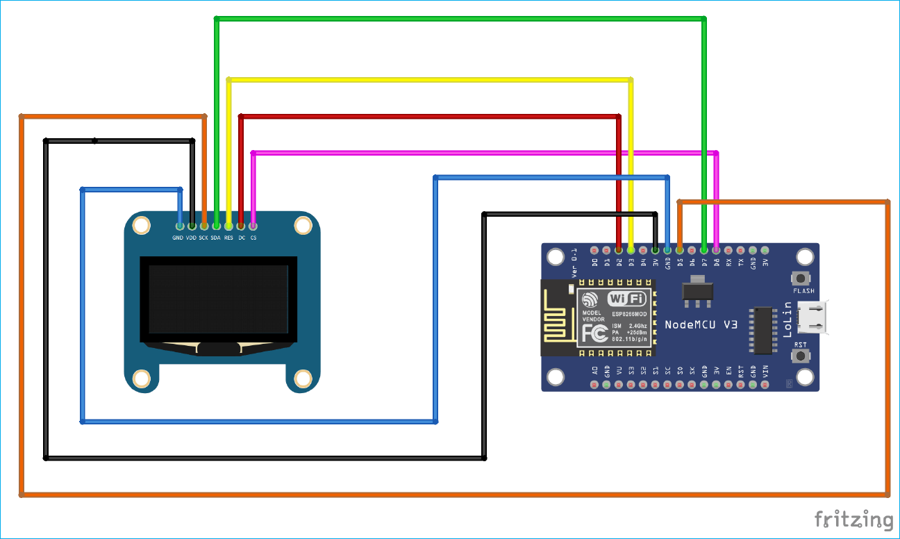
This 7-pin OLED display communicates with ESP8266 module using SPI protocol, below are the circuit diagram and connections table to connect OLED SPI pins with NodeMCU to display Internet time.
|
No. |
OLED Display |
NodeMCU |
|
1 |
GND |
GND |
|
2 |
VDD |
3.3V |
|
3 |
SCK |
D5 |
|
4 |
MOSI (SPI) or SDA (I2C) |
D7 |
|
5 |
RESET |
D3 |
|
6 |
DC |
D2 |
|
7 |
CS |
D8 |
To learn more this Monochrome 7-pin OLED display and its interfacing with ESP8266 NodeMCU, follow the link.
Code Explanation
First we have to download and install NTP library into ESP8266. There are many libraries available for NTP Client. You can install any of them from Arduino IDE. In this tutorial I have installed NTPClient library by Taranais because it is easy to use and have functions to get date and time from NTP servers. ESP8266 NodeMCU can be easily programmed using Arduino IDE.
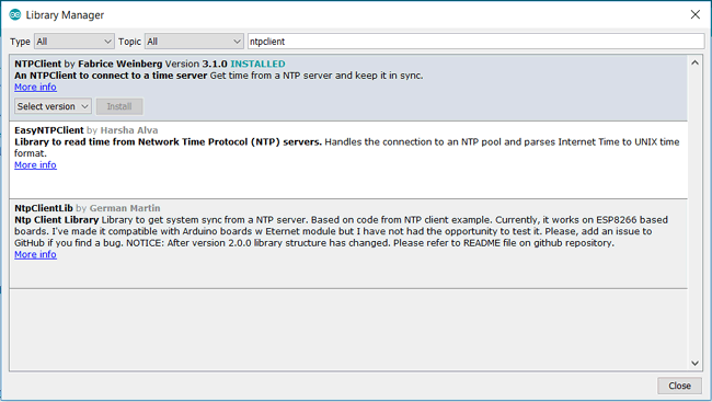
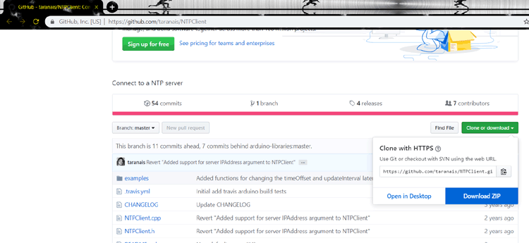
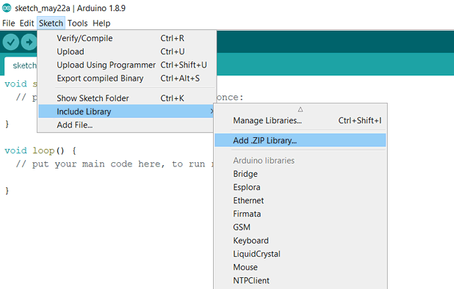
To install the NTP library, first download the library using above link and then install it using Arduino IDE. To install it go to Sketch > Include Library > Add .ZIP Library, then open the Zip folder by going to the location where you have downloaded the zip folder and restart the Arduino IDE.
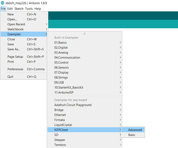
NTPClient library comes with examples. Open Arduino IDE and Goto Examples > NTPClient > Advanced. The code given in this sketch displays the time from NTP server on the serial monitor. We will use this sketch to display current time and date on OLED display.
Complete code is available at the end of this tutorial, here I have explained few important part of the code.
ESP8266WiFi library provides ESP8266 specific Wi-Fi routines to connect to network. WiFiUDP.h handles sending and receiving UDP packages. Since we are using SPI protocol to interface OLED with NodeMCU therefore we will import “SPI.h” library. And “Adafruit_GFX.h” and “Adafruit_SSD1306.h” are used for OLED Display.
#include <NTPClient.h>
#include <ESP8266WiFi.h> // provides ESP8266 specific Wi-Fi routines we are calling to connect to network
#include <WiFiUdp.h> //handles sending and receiving of UDP packages
#include <SPI.h> // SPI for interfacing OLED with NodeMCU
#include <Adafruit_GFX.h>
#include <Adafruit_SSD1306.h>
Our OLED size is 128x64 so we are setting screen width and height as 128 and 64 respectively. So define the variables for OLED pins connected to NodeMCU for SPI communication.
#define SCREEN_WIDTH 128 // OLED display width, in pixels
#define SCREEN_HEIGHT 64 // OLED display height, in pixels

// Declaration for SSD1306 display connected using software SPI (default case):
#define OLED_MOSI   D7
#define OLED_CLK   D5
#define OLED_DC    D2
#define OLED_CS    D8
#define OLED_RESET D3
Adafruit_SSD1306 display(SCREEN_WIDTH, SCREEN_HEIGHT,OLED_MOSI, OLED_CLK, OLED_DC, OLED_RESET, OLED_CS);
Replace “your_ssid” and “your_password” with your Wi-Fi SSID and password in the below lines of code.
const char *ssid     = "your_ssid";
const char *password = "your_password";
Set up WI-Fi connection by giving SSID and password to WiFi.begin function. The connection of ESP8266 takes some time to get connected to NodeMCU so we have to wait till it gets connected.
WiFi.begin(ssid, password);
  while ( WiFi.status() != WL_CONNECTED ) {
    delay ( 500 );
    Serial.print ( "." );
  }
To request date and time, initialize time client with address of NTP servers. For better accuracy choose the address of NTP servers which are close to your geographical area. Here we use “pool.ntp.org” which gives servers from worldwide. If you wish to choose servers from Asia you can use “asia.pool.ntp.org”. timeClient also takes UTC time offset in milliseconds of your timezone. For instance, UTC offset for India is +5:30 so we convert this offset in milliseconds which is equal to 5*60*60+30*60 = 19800.
|
Area |
UTC time offset(hours and minutes) |
UTC time offset(seconds) |
|
INDIA |
+5:30 |
19800 |
|
LONDON |
0:00 |
0 |
|
NEW YORK |
-5:00 |
-18000 |
WiFiUDP ntpUDP;
NTPClient timeClient(ntpUDP, "pool.ntp.org", 19800,60000);
SSD1306_SWITCHCAPVCC is given to generate 3.3V internally to initialize the display. When the OLED starts it displays “WELCOME TO CIRCUIT DIGEST” with text size 2 and color BLUE for 3 seconds.
if(!display.begin(SSD1306_SWITCHCAPVCC))
  {
    Serial.println(F("SSD1306 allocation failed"));
    for(;;); // Don't proceed, loop forever
  }
  display.clearDisplay();
  display.setTextSize(2); // Draw 2X-scale text
  display.setTextColor(BLUE);
  display.setCursor(5, 2);
  display.println("WELCOME TO");
  display.println("  CIRCUIT");
  display.println("  DIGEST");
  display.display();
  delay(3000);
NTP client is initialized using begin() function to set date and time from NTP servers.
timeClient.begin();
Update() function is used to receive the date and time whenever we request to NTP servers.
timeClient.update();
Baud rate of 115200 is set to print the time on serial monitor.
Serial.begin(115200);
Serial.println(timeClient.getFormattedTime());
getHours(), getMinutes(), getSeconds(), getDay are the library function and gives the current hour, minutes, seconds and day from NTP server. Code below is used to differentiate time between AM and PM. If the hour we get using getHours() is greater than 12 then we set that time as PM else its AM.
int hh = timeClient.getHours();
int mm = timeClient.getMinutes();
int ss = timeClient.getSeconds();
int day = timeClient.getDay();

if(hh>12)
  {
    hh=hh-12;
    display.print(hh);
    display.print(":");
    display.print(mm);
    display.print(":");
    display.print(ss);
    display.println(" PM");
  }
  else
  {
    display.print(hh);
    display.print(":");
    display.print(mm);
    display.print(":");
    display.print(ss);
    display.println(" AM");
  }
  int day = timeClient.getDay();
  display.println("'"+arr_days[day]+"'");
getFormattedDate() is used get date in “yyyy-mm-dd” format from NTP server. This function gives date and time in “yyyy-mm-dd T hh:mm:ss format. But we need only date so we have to split this string which is stored in date_time format till “T” which is done by substring() function and then store the date in “date” variable.
date_time = timeClient.getFormattedDate();
  int index_date = date_time.indexOf("T");
  String date = date_time.substring(0, index_date);
  Serial.println(date);
  display.println(date);
  display.display();
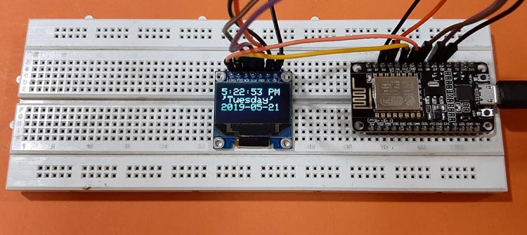
This is how the OLED Internet time Clock will look finally:

Complete Project Code
#include <NTPClient.h>

#include <ESP8266WiFi.h> // provides ESP8266 specific Wi-Fi routines we are calling to connect to network

#include <WiFiUdp.h> //handles sending and receiving of UDP packages

#include <SPI.h> // SPI for interfacing OLED with NodeMCU

#include <Adafruit_GFX.h>

#include <Adafruit_SSD1306.h>
#define SCREEN_WIDTH 128 // OLED display width, in pixels

#define SCREEN_HEIGHT 64 // OLED display height, in pixels

// Declaration for SSD1306 display connected using software SPI (default case):

#define OLED_MOSI   D7

#define OLED_CLK   D5

#define OLED_DC    D2

#define OLED_CS    D8

#define OLED_RESET D3

Adafruit_SSD1306 display(SCREEN_WIDTH, SCREEN_HEIGHT,OLED_MOSI, OLED_CLK, OLED_DC, OLED_RESET, OLED_CS);
const char *ssid     = "CircuitLoop";

const char *password = "circuitdigest101";
WiFiUDP ntpUDP;

NTPClient timeClient(ntpUDP, "pool.ntp.org", 19800,60000);

String arr_days[]={"Sunday","Monday","Tuesday","Wednesday","Thursday","Friday","Saturday"};

String date_time;

// You can specify the time server pool and the offset (in seconds, can be

// changed later with setTimeOffset() ). Additionaly you can specify the

// update interval (in milliseconds, can be changed using setUpdateInterval() ).


void setup(){

  Serial.begin(115200);

  WiFi.begin(ssid, password);
  while ( WiFi.status() != WL_CONNECTED ) {

    delay ( 500 );

    Serial.print ( "." );

  }
  if(!display.begin(SSD1306_SWITCHCAPVCC))

  {

    Serial.println(F("SSD1306 allocation failed"));

    for(;;); // Don't proceed, loop forever

  }

  display.clearDisplay();

  display.setTextSize(2); // Draw 2X-scale text

  display.setTextColor(WHITE);

  display.setCursor(5, 2);

  display.println("WELCOME TO");

  display.println("  CIRCUIT");

  display.println("  DIGEST");

  display.display();

  delay(3000);

  timeClient.begin();

}
void loop() {

  timeClient.update();


  display.clearDisplay();


  Serial.println(timeClient.getFormattedTime());


  display.setTextSize(2); // Draw 2X-scale text

  display.setTextColor(BLUE);

  display.setCursor(0, 2);

  int hh = timeClient.getHours();

  int mm = timeClient.getMinutes();

  int ss = timeClient.getSeconds();


  if(hh>12)

  {

    hh=hh-12;

    display.print(hh);

    display.print(":");

    display.print(mm);

    display.print(":");

    display.print(ss);

    display.println(" PM");

  }

  else

  {

    display.print(hh);

    display.print(":");

    display.print(mm);

    display.print(":");

    display.print(ss);

    display.println(" AM");

  }
  int day = timeClient.getDay();

  display.println("'"+arr_days[day]+"'");


  date_time = timeClient.getFormattedDate();

  int index_date = date_time.indexOf("T");

  String date = date_time.substring(0, index_date);

  Serial.println(date);

  display.println(date);

  display.display();      // Show initial text

}

