This project is nothing but a simple All-in-One Car Accessory System
Have you ever thought about how many gadgets people use in their cars? There are dashcams to record what's happening on the road, OBD (On-Board Diagnostics) scanners to check how the car is running, and GPS (GNSS) trackers to follow the car's location. Each of these is a separate device that you need to buy and set up in your car. Wouldn't it be easier if all of these functions were combined into one device? That's exactly what I set out to create!
What My Project Does?
My project is a smart car system that combines multiple accessories into a single device. It can:
- Act as a dashcam, recording video while you're driving.
- Monitor your car’s health using OBD-II (the port in your car that mechanics plug into to get vehicle data like speed, engine temperature, and much more).
- Track your car’s location with a GNSS module (which is like GPS).
- Save all this information on an SD card for easy access later.
- Send the collected data to an IoT dashboard over the internet, so you can see it remotely.

Components Required
OBD-II CAN-BUS DEVELOPMENT KIT
DC-DC buck converter
GNSS Module
Portable Router / LTE Module(optional)
How It Works?
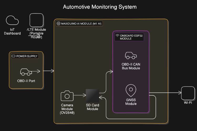
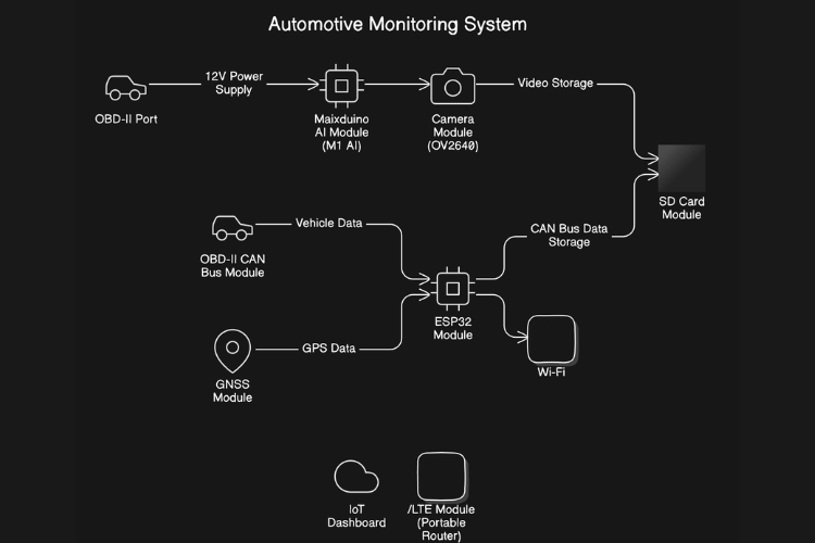
At the heart of the project is a device called the Maixduino. This board is like a small computer that connects to all the different parts of the system. Here’s a breakdown of what’s connected to it:
- A camera captures real-time video. This video is saved onto the SD card.
- The OBD-II connector is hooked up to the car’s diagnostic system. This lets the system capture important data from the car like engine health, speed, and fuel levels.
- A GNSS module tracks the car’s location, so you can always know where your vehicle is.
- All the information from the camera and car sensors is stored on an SD card.
- Onboard ESP32 Wroom module allows the system to send data to an IoT dashboard via WiFi/Hotspot device. This means you can access your car's data, like video and diagnostics, remotely through the internet.
Why This Project is Special?
What makes this project unique is that instead of having multiple devices in your car, you only need this one system. It takes care of everything—recording video, tracking your car’s health, knowing where it is, and storing all that information safely. Plus, because we’re using the Maixduino, this system has the potential for future upgrades. Imagine adding features like a touchscreen, a voice assistant, or even a music system!
In the future, this project could become even more advanced. With more work, we could develop it into a complete car entertainment and control system, handling things like navigation, playing music, or even helping the driver with AI-powered assistance.
I have made 2 different codes from the example codes to have an idea of functionality. Following codes are just simple compiled version of separate codes of different functions. It needs to be tested and validated according to proper libraries and hardware connection changes once Hardware is in hand.
Since the Maixduino AI module (M1AI / K210) and the ESP32 module are separate components with different functionalities, there are two separate codes:
Maixduino AI Module (M1 AI): This module will handle camera (dashcam) functionality, video recording, and SD card storage.
ESP32 Module: This module will manage CAN bus (OBD-II) data collection, GPS tracking, and data transmission to the IoT dashboard.
Code for Maixduino AI Module (M1 AI) (Handles Camera, TFT display, and SD Card Recording)
#include <Sipeed_OV2640.h>#include <Sipeed_SD.h>#include <Sipeed_FS.h>#include <Maix_Speech_Recognition.h>#include <TFT_eSPI.h> // TFT display library for MaixduinoSipeed_OV2640 camera; // Camera moduleFile videoFile; // File object for SD card videoTFT_eSPI tft = TFT_eSPI(); // TFT display objectvoid setup() {Serial.begin(115200);// Initialize TFT displaytft.begin();tft.setRotation(3); // Adjust orientation as neededtft.fillScreen(TFT_BLACK); // Clear the screentft.setTextColor(TFT_WHITE, TFT_BLACK);tft.setTextSize(2);tft.setCursor(10, 10);tft.println("Initializing Camera...");// Initialize cameraif (!camera.begin(QVGA)) { // Use QVGA resolution (320x240)Serial.println("Failed to initialize camera");tft.println("Camera initialization failed!");while (1);}Serial.println("Camera initialized");tft.println("Camera initialized");// Initialize SD cardif (!SD.begin()) {Serial.println("Failed to initialize SD card");tft.println("SD card init failed!");while (1);}tft.println("SD card initialized");// Open video filevideoFile = SD.open("/dashcam_video.avi", FILE_WRITE);if (!videoFile) {Serial.println("Failed to open video file");tft.println("Failed to open video file");while (1);}Serial.println("SD card initialized and video file opened");tft.println("Video file opened");}void loop() {// Capture a video framecamera.run();uint8_t* img = camera.getfb(); // Get frame buffer// Display the camera feed on TFT screentft.pushImage(0, 0, camera.width(), camera.height(), (uint16_t*)img);// Write video frame to SD cardvideoFile.write(img, camera.width() * camera.height()); // Save frame to file// Display status on Serial (Optional for debugging)Serial.println("Frame captured");delay(100); // Capture at 10 FPS}
Code for ESP32 Module (Handles OBD-II Data, GPS, and IoT Dashboard)
#include <mcp_can.h>#include <SPI.h>#include <Wire.h>#include <WiFi.h>#include <HTTPClient.h>#include <TinyGPS++.h>// CAN Bus (OBD-II)const int SPI_CS_PIN = 10;MCP_CAN CAN(SPI_CS_PIN); // Set SPI CS pin for CAN module// Wi-Fi Configurationconst char* ssid = "your-SSID";const char* password = "your-password";const char* serverUrl = "http://your-iot-dashboard.com/data";// GNSS Module (TinyGPS++)TinyGPSPlus gps;HardwareSerial ss(1); // Use Serial1 for GNSS (RX=4, TX=3)// Global Variables for OBD-II Dataint rpm = 0;int temperature = 0;// Function to send OBD-II and GNSS data to IoT dashboardvoid sendDataToDashboard(int rpm, int temperature, float latitude, float longitude) {if (WiFi.status() == WL_CONNECTED) {HTTPClient http;http.begin(serverUrl);http.addHeader("Content-Type", "application/json");String jsonData = "{"rpm":" + String(rpm) + ","temperature":" + String(temperature) +","latitude":" + String(latitude, 6) + ","longitude":" + String(longitude, 6) + "}";int httpResponseCode = http.POST(jsonData);if (httpResponseCode > 0) {String response = http.getString();Serial.println("Data sent successfully: " + response);} else {Serial.println("Error sending data");}http.end();}}// Setup Functionvoid setup() {Serial.begin(115200);// Initialize CAN bus (OBD-II)if (CAN.begin(CAN_500KBPS) == CAN_OK) {Serial.println("CAN Bus Initialized");} else {Serial.println("CAN Bus Initialization Failed");while (1);}// Connect to Wi-FiWiFi.begin(ssid, password);while (WiFi.status() != WL_CONNECTED) {delay(1000);Serial.println("Connecting to WiFi...");}Serial.println("Connected to WiFi");// Initialize GNSS (GPS)ss.begin(9600, SERIAL_8N1, 4, 3); // RX=4, TX=3 for GPS module}// Main Loopvoid loop() {// Fetch OBD-II data from CAN busif (CAN_MSGAVAIL == CAN.checkReceive()) {long unsigned int rxId;unsigned char len = 0;unsigned char rxBuf[8];CAN.readMsgBuf(&rxId, &len, rxBuf);// Example: Parse OBD-II data (modify based on your PID values)rpm = (rxBuf[0] << 8) | rxBuf[1]; // Example: Calculate RPMtemperature = rxBuf[2]; // Example: Temperature data// Print OBD-II data to SerialSerial.print("RPM: ");Serial.println(rpm);Serial.print("Temp: ");Serial.println(temperature);}// Fetch GNSS (GPS) datawhile (ss.available() > 0) {gps.encode(ss.read());}// If GPS location is available, print and send dataif (gps.location.isUpdated()) {float latitude = gps.location.lat();float longitude = gps.location.lng();Serial.print("Latitude: ");Serial.println(latitude, 6);Serial.print("Longitude: ");Serial.println(longitude, 6);// Send OBD-II and GPS data to IoT dashboardsendDataToDashboard(rpm, temperature, latitude, longitude);}delay(1000); // Update data every second}
Explanation of the Two Codes
Maixduino AI Module (M1 AI) Code:
TFT Initialization: We initialize the TFT display using the TFT_eSPI library. The screen is cleared and a message is displayed to let the user know the camera and SD card are being initialized.
Camera Feed Display: In the loop() function, after capturing a frame from the camera, the frame is displayed in real-time on the TFT display using the tft.pushImage() function.
Video Frame to SD Card: The captured frame is also written to the SD card simultaneously.
ESP32 Module Code:
OBD-II Data via CAN Bus: This code uses the MCP_CAN library to read the OBD-II data from the car's CAN bus. In this example, it fetches the RPM and temperature, but this can be expanded to include other parameters like speed, fuel consumption, etc.
GNSS (GPS) Data: The TinyGPS++ library reads data from the GNSS module, which provides real-time latitude and longitude. It is updated continuously and sent to the IoT dashboard.
Wi-Fi IoT Communication: The ESP32 connects to the IoT dashboard via Wi-Fi. The OBD-II data and GPS coordinates are sent to the server using HTTP POST requests.


