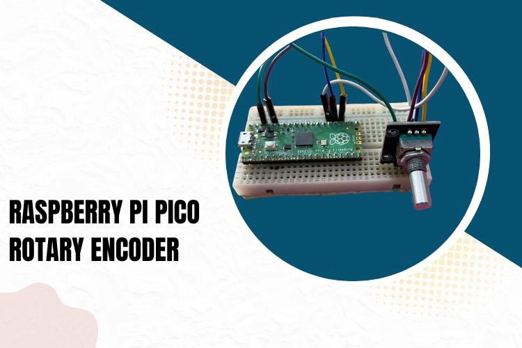
In this blog post, we will explore how to interface a rotary encoder with the Raspberry Pi Pico microcontroller. Rotary encoders are popular input devices that can be used to measure and control the position and rotation of a shaft. The Raspberry Pi Pico, with its GPIO pins and capabilities, provides an excellent platform for integrating a rotary encoder into your projects. In this step-by-step guide, we will walk through the process of connecting a rotary encoder to the Raspberry Pi Pico and writing the code to read and interpret its input.
Difference between Rotary Encoders and Potentiometers
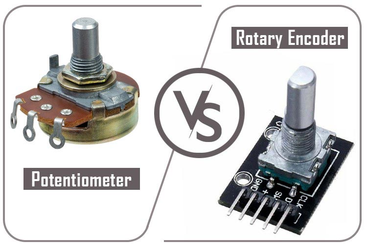
Though the potentiometers and rotary encoders may look similar, they both are very different from each other.
The primary difference between the rotary encoders and the potentiometer is its utility. The rotary encoders are used where we need to know the change in the motion of the knob while potentiometers are used where exact position of knob is to be measured.
The degree of motion is also very different while a rotary encoder can move in any direction continuously, the potentiometer can only move around 270 degrees
Working of Rotary Encoder
Imagine you have a knob that you can turn in either direction. A rotary encoder is like a clever device that can detect and measure the movement and rotation of that knob. It can tell you how much the knob has been turned and in which direction.
A rotary encoder typically consists of a rotating shaft and two parts called the "A" and "B" channels. As you turn the knob, these channels produce a series of electrical signals (when connected to a common ground) that the encoder can understand. It uses these signals to keep track of the knob's position and movement.
The great thing about a rotary encoder is that it can provide precise and accurate feedback about how much the knob has been turned. It can detect even the smallest rotations, whether you're turning the knob slowly or quickly. It can also detect when it is pushed like a button in the center.
Rotary encoders are commonly used in various applications. For example, they can be found in volume control knobs on audio equipment, as well as in navigation systems, industrial machinery, and robotics. They provide a convenient and reliable way to input rotational movements into electronic systems.
Rotary Encoder Pinout
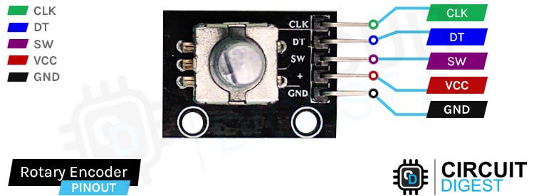
Here's the explanation of each pin:
SW (Switch): This pin corresponds to the integrated push-button switch on the rotary encoder. When the button is pressed, this pin typically outputs a logical LOW or GND signal, indicating a button press event.
VCC (Positive Supply): This pin is connected to the positive supply voltage of the circuit, often referred to as Vcc. It provides the power supply for the rotary encoder.
GND (Ground): This pin is connected to the ground or 0V reference of the circuit. It provides the common ground connection for the rotary encoder.
DT (Data) or Channel B: This pin provides additional signals to help determine the direction of rotation. By analyzing the order and timing of the signals from this pin and the CLK pin, the direction of rotation can be determined.
CLK (Clock) or Channel A: This pin outputs pulses or signals that indicate the rotation of the encoder. Each pulse corresponds to a specific amount of rotation in either clockwise or counterclockwise direction.
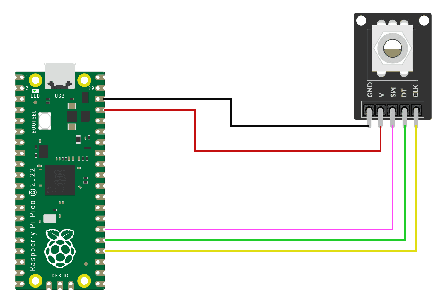
Circuit Diagram of Raspberry Pi Pico and Rotary Encoder Interfacing
- Connect the VCC pin of the rotary encoder to the 3.3V pin on the Pico.
- Connect the GND pin of the rotary encoder to any GND pin on the Pico.
- Connect the DATA pin of the rotary encoder to a digital input pin on the Pico (e.g., pin 25).
- Connect the CLK pin of the rotary encoder to another digital input pin on the Pico (e.g., pin 24).
- If your rotary encoder has a built-in switch, you can connect the SW pin to a digital input pin on the pico (e.g., pin 26).
Code for Raspberry Pi Pico and Rotary Encoder Interfacing
Next you need to upload code on the pico. If you already know how to do that, you can move forward with the code. If not you can refer to the blog on circuit digest where we explain how you can program your pico using thonny ide.
This code includes an additional check for a keyboard interrupt to gracefully exit the program and it also shows output when the center button is pushed. Here's an explanation of each line:
import time
from rotary_irq_rp2 import RotaryIRQ
from machine import Pin
These lines import the necessary modules for the code to run.
SW = Pin(20, Pin.IN, Pin.PULL_UP)
This line sets up a Pin object named SW on GPIO pin 20. It is configured as an input pin with a pull-up resistor.
r = RotaryIRQ(pin_num_clk=18,
              pin_num_dt=19,
              min_val=0,
              reverse=False,
              range_mode=RotaryIRQ.RANGE_UNBOUNDED)
This line creates a RotaryIRQ object named r. It sets up the rotary encoder's pins and parameters, similar to the previous code.
val_old = r.value()
This line initializes the variable val_old with the initial value of the rotary encoder's position.
while True:
    try:
        val_new = r.value()
        if SW.value() == 0:
            print("Button Pressed")
            print("Selected Number is:", val_new)
            while SW.value() == 0:
                continue
        if val_old != val_new:
            val_old = val_new
            print('result =', val_new)
        time.sleep_ms(50)
    except KeyboardInterrupt:
        break
This is the main loop of the program. It continuously reads the rotary encoder's value using r.value() and stores it in val_new. If the button connected to pin 20 (SW) is pressed (its value is 0), it prints "Button Pressed" and the current value of the rotary encoder (val_new). It continues printing the value while the button is held down (SW.value() == 0). If there is a change in the encoder's value (val_old is different from val_new), it updates val_old and prints the new value. The time.sleep_ms(50) pauses the program for 50 milliseconds before the next iteration of the loop. If a keyboard interrupt (Ctrl+C) is detected, the program breaks out of the loop and gracefully exits.
Output of this code looks as follows:-
You can see above that selected output is printed when the center button is pushed.
Now you can play a bit with this encoder. Maybe make a project with it like controlling a geared dc motor or a servo motor. If you have any doubts you can let us know in the comment section. Hope you learned something useful today. See you soon.
Projects using Raspberry Pi Pico
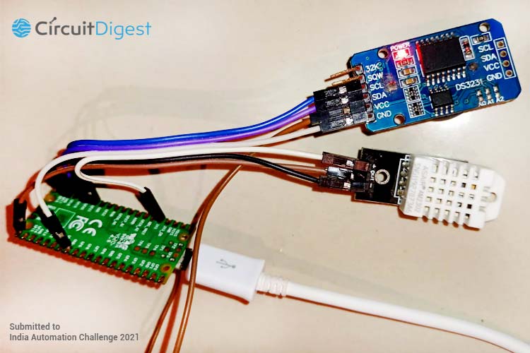
Discover the fascinating world of temperature monitoring with our latest project, the Temperature Data Logger. Leveraging the power of Raspberry Pi Pico and the precision of the DHT22 temperature sensor, we have developed a versatile and efficient solution for tracking temperature variations. In this blog post, we delve into the step-by-step process of setting up the hardware, configuring the software, and logging temperature data with impressive accuracy.
Learn about the exciting world of robotics as we guide you through the process of creating a Line Follower Robot using the Raspberry Pi Pico microcontroller. In this blog post, we'll provide you with step-by-step instructions and insights to help you build your own robot that can follow a line autonomously. Let's dive in and explore the possibilities of robotics!
Explore the untapped potential of your Raspberry Pi Pico microcontroller as we delve into the realm of dual core programming using MicroPython. In this blog post, we will guide you through the process of harnessing the power of both cores on the Raspberry Pi Pico, unlocking new possibilities for your projects. Get ready to elevate your programming skills and maximize the capabilities of your microcontroller.
Supporting Files
You can download all the necessary files from the Circuit Digest GitHub repo, from the following link
Complete Project Code
import time
from rotary_irq_rp2 import RotaryIRQ
from machine import Pin
SW=Pin(20,Pin.IN,Pin.PULL_UP)
r = RotaryIRQ(pin_num_clk=18,
        pin_num_dt=19,
        min_val=0,
        reverse=False,
        range_mode=RotaryIRQ.RANGE_UNBOUNDED)
val_old = r.value()
while True:
   try:
     val_new = r.value()
     if SW.value()==0:
       print("Button Pressed")
       print("Selected Number is : ",val_new)
       while SW.value()==0:
         continue
     if val_old != val_new:
       val_old = val_new
       print('result =', val_new)
     time.sleep_ms(50)
   except     KeyboardInterrupt:
     break

