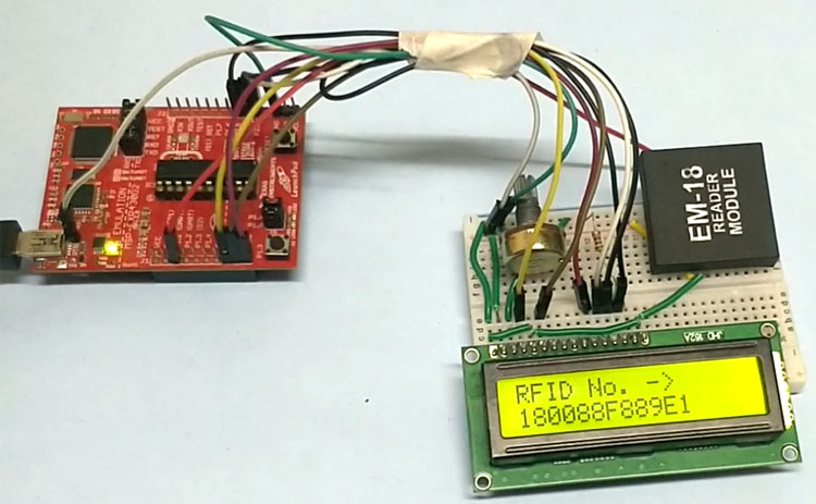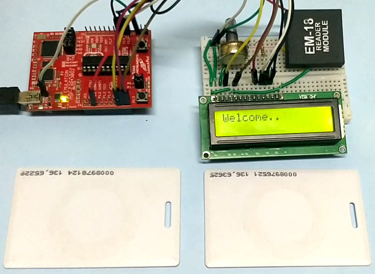
In this tutorial we design a system to read the RFID cards using MSP430 and RFID Reader. RFID stands for Radio Frequency Identification. Each card has a unique ID and this makes it a perfect choice for many authentication applications, like in offices, shopping malls and in many other places where only the person with authorization card is allowed to enter inside. RFID is used in shopping malls to stop a theft from happening, where the product will be tagged with RFID chip and if anyone leaves the building with the RFID chip an alarm is raised automatically and so the theft is stopped. The RFID tag is designed as small as grain of sand. The RFID authentication systems are easy to design and are cheap in cost. Some schools and colleges nowadays use RFID as attendance register.
Materials Required
1. MSP430 Launchpad
2. EM-18 (RFID reader module)
3. 16*2 LCD
4. Potentiometer
5. Breadboard
6. Jumper wires
Software: Energia IDE
EM-18 RFID Reader
Each RFID card has a unique ID embedded in it and a RFID reader is used to read the RFID card no. EM-18 RFID reader operates at 125 KHz and it comes with an on-chip antenna and it can be powered with 5V power supply. It provides serial output along with weigand output. The range is around 8-12cm. serial communication parameters are 9600bps, 8 data bits, 1 stop bit. This wireless RF Identification is used in many systems like
Check all the RFID Projects here.
The output provided by EM-18 RFID reader is in 12 digit ASCII format. Out of 12 digits first 10 digits are card number and the last two digits are the XOR result of the card number. Last two digits are used for error checking.


For example, card number is 0200107D0D62 read from the reader then the card number on the card will be as below.
02 – preamble
00107D0D = 1080589 in decimal.
62 is XOR value for (02 XOR 00 XOR 10 XOR 7D XOR 0D).
Hence number on the card is 0001080589.
MSP430 RFID Reader Circuit Diagram and Working
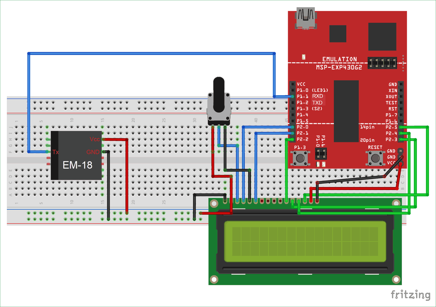
We will use Hardware UART of MSP430 so, make sure RXD and TXD jumpers on the board are on HW UART mode. Then connect Tx of EM-18 to RXD(P1.1) of MSP430.
Before going to further we need to understand about the serial communication. The RFID module here sends data to the controller in serial. It has other mode of communication but for easy communication we are choosing RS232. The RS232 pin of module is connected to RXD pin of MSP430.
The data sent by the RFID module goes as:

Now for setting up a connection between RFID reader and MSP430, we need to enable the serial communication in MSP430. The serial communication enabling in MSP430 can be done by using a single command.
Serial.begin(9600);
data = Serial.read();
As shown in figure above, the communication of RFID is done by a BAUD rate of 9600 bits per second. So for MSP430 to establish such baud rate and to start serial communication we use command "Serial.begin(9600);". Here 9600 is the baud rate and is changeable.
Now once baud rate is set, MSP is ready to receive the serial data. This data is picked up by command “data = Serial.read();”. By this command serial data is taken in ‘data’ named integer.
Once a card is brought near reader, the reader reads the serial data and sends it to MSP, the MSP will be programmed to show that value in LCD, so we will have ID of card on LCD.

Code and Explanation
We will write our code in Energia IDE. It is same as Arduino IDE and easy to use. Complete code is given at the end of this project, here we are explaining few parts of it.
First, include library for LCD display and declare char array to store RFID number.
#include <LiquidCrystal.h>
LiquidCrystal lcd(P2_0, P2_1, P2_2, P2_3, P2_4, P2_5);
char input[12];
In setup function, enable LCD and serial communication by defining Baud rate of 9600.
void setup()
{
  lcd.begin(16, 2);
  Serial.begin(9600);
...
..
In loop function, we will check serial data is available or not. If available, store the data in input[count] array from Serial.read() and display it on the LCD one by one using while loop.
while(Serial.available() && count < 12)      // Read 12 characters and store them in input array
      {
      input[count] = Serial.read();      //storing 12 characters one by one
              Serial.print(input[count]);
             lcd.print(input[count]);
                 delay(300);
                      count++;
                 if (count==12)
                 {
                 lcd.print("                      ");
                 count = 0;   // once 12 characters are read get to start and wait for second ID
…
…
This is how we can read and display the RFID number on LCD using MSP430 Launchpad. Now you can further extend this project and can build Attendance system, voting system, security system etc.
Complete Project Code
#include <LiquidCrystal.h>

LiquidCrystal lcd(P2_0, P2_1, P2_2, P2_3, P2_4, P2_5);

char input[12];

int count = 0;

void setup()

{

  lcd.begin(16, 2);

  Serial.begin(9600);

  lcd.setCursor(0, 0);

  lcd.print("Welcome..");

  delay(3000);

  lcd.clear();

  lcd.print("Place Card to");

  lcd.setCursor(0, 1);

  lcd.print("scan");

  }

 void loop()

{

 if(Serial.available()==0){

  lcd.clear();

  lcd.setCursor(0, 0);

     lcd.print("Place Card to scan");

  for (int positionCounter = 0; positionCounter < 13; positionCounter++) {

    // scroll one position left:

    lcd.scrollDisplayLeft();

    // wait a bit:

   delay(150);

  }

 }

  if(Serial.available()>0){

  lcd.clear();

  lcd.setCursor(0, 0);

  lcd.print("RFID No. ->");

  lcd.setCursor(0, 1);

  delay(30);

  }

   while(Serial.available() && count < 12)          // Read 12 characters and store them in input array

   {

    input[count] = Serial.read(); //storing 12 characters

    Serial.print(input[count]);

    lcd.print(input[count]);

    delay(300);

    count++;


    if (count==12)

    {

     lcd.print("                      ");

     count = 0;           // once 12 characters are read get to start and wait for  second ID

     lcd.setCursor(0, 1);       //move courser to start

    }

  }

 delay(3000);

}


