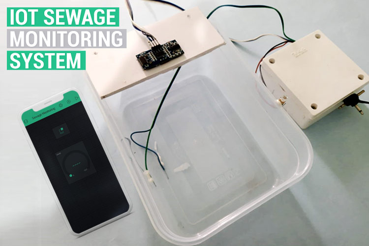
Sewage management is an important aspect of municipal infrastructure and undoubtedly, it affects our daily hygiene. Poor sewage/drainage management can cause urban floods which is most common in crowded cities. This problem can be addressed by using Smart Sewage Management Device based on IoT and Sensor Technology.
In this article, we are going to build a smart device that can sense when the drainage system gets blocked and if the water overflows because of this blockage, we will send a notification to the municipal authority for the necessary action. Moreover, using the Android application, the status of the drainage system can be monitored in real-time. This project is very similar to a normal water level indicator project that we have build earlier, but instead of water, we will be sensing sewage overflow and monitor it online using IoT.
Components Required
- ESP8266 NodeMCU
- HCSR04 Ultrasonic sensor
- Float sensor/Conductive electrodes
- Breadboard Power supply
- Connecting wires
- LED
- 12V, 1 AMP DC Adopter
Working of Sewage Monitoring Project
In the project, two sensors were used as input devices, i.e. Ultrasonic sensor which is used to detect the blockage, and the Water level sensor which is used to detect the overflow of water. The information from these sensors is received and processed in the ESP8266 which acts as both Microcontroller and WiFi module. The below image represents the block diagram for our project.
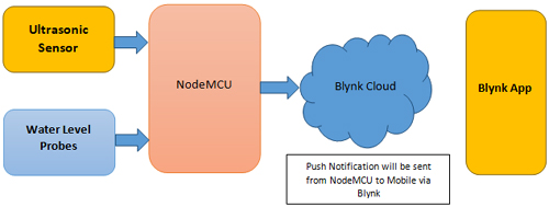
The ESP8266 performs all the logical and mathematical operations inside and sends the appropriate signals to the Blynk cloud for the necessary actions. Here, the real-time ultrasonic distance is sent to the Blynk application, and also a push notification is sent to the mobile in case of Blockage or Overflow.
IoT based Sewage Monitoring Circuit Diagram
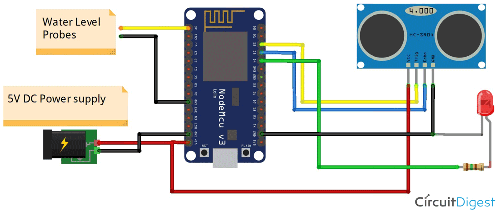
First, the circuit can be connected as per the circuit diagram of the sewage monitoring device shown below.
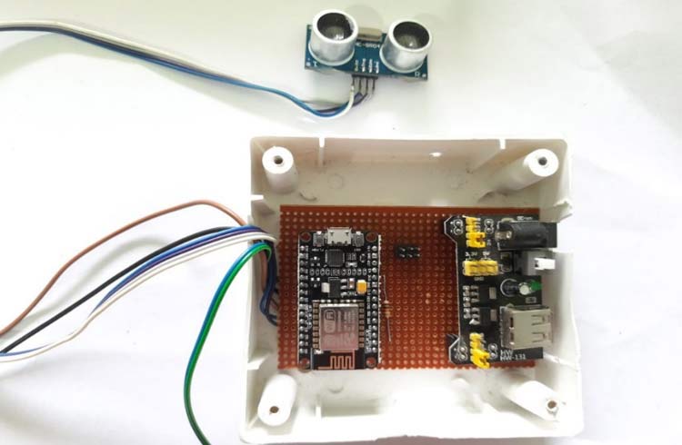
Here, two conductors were used as water level detectors which can also be replaced with float sensors in the similar fashion. I have soldered the circuit in a perf board as shown below.
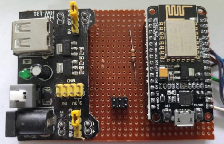
Then for external protection, it is encased within a Plastic enclosure and the final assembly looks like below:
Setting up Blynk Application for Remote Sewage Monitoring
Blynk is an application that can run over Android and iOS devices to control any IoT devices using our smartphones. We can create our own Graphical User Interface to design our IoT application GUI. You can also check out all other Blynk IoT projects that we have built earlier. Here, we will set up our Blynk application for this project to monitor the sewage status.
Before the setup, download the Blynk Application from the Google Play Store (iOS users can download it from App Store). After installation, sign-up using your email id and Password.
Creating a new Project on Blynk:
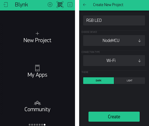
After successful installation, open the application, and there you will get a screen with the option “New Project”. Click there and a new screen will pop up, where we need to set the parameters like Project name, Board, and Connection type. In this project, select the device as NodeMCU and connection type as Wi-Fi and click on “Create”.
After the successful Creation of the Project, we will get an Authenticate ID on our registered email. Save the Authenticate ID for future reference.
Creating the GUI:
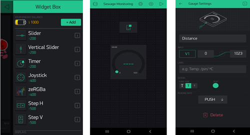
Open the project in Blynk, click on the “+” sign where we will get the widgets that we can use in this project. Here a “Gauge” widget is selected to display the Distance of clearance and a “Notification” widget is selected to receive the notifications from NodeMCU. In the Gauge setting, necessary changes can be done like the Name of parameters, Pin number which is V1 in this project.
Programming NodeMCU for Sewage Monitoring
To upload code to NodeMCU, follow the steps below:
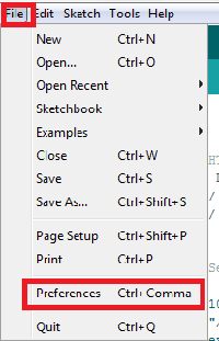
1. Open Arduino IDE, then go to File-->Preferences-->Settings.
2. Type https://arduino.esp8266.com/stable/package_esp8266com_index.json in the ‘Additional Board Manager URL’ field and click ‘Ok’.
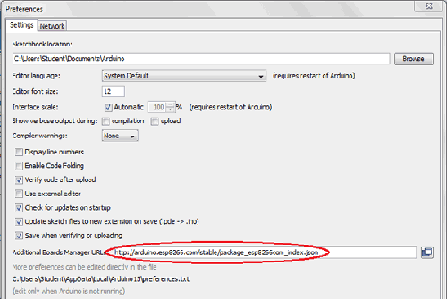
3. Now go to Tools--> Board--> Boards Manager. In Boards Manager window, Type ESP8266 in the search box, select the latest version of the board and click on install.
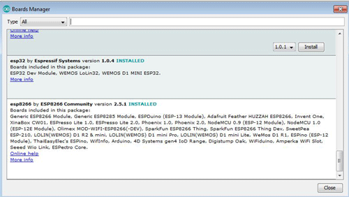
4. After the installation is complete, go to Tools-->Board--> and select NodeMCU 1.0(ESP-12E Module). Now, you can program NodeMCU with Arduino IDE.
After the above setup for programming NodeMCU, we have to upload the complete code to ESP8266 NodeMCU. First, we have to include all the required library files in our code.
Start the code by including all the required library files in the code like ESP8266WiFi.h for ESP8266 board, etc.
Here “BlynkSimpleEsp8266.h” is used to integrate Blynk with the ESP8266 module. To download the package, Open Arduino IDE, then go to the tab Sketch and click on the option Include Library--> Manage Libraries. Then search for Blynk in the search box and download and install the Blynk package for ESP8266.
#define BLYNK_PRINT Serial
#include <BlynkSimpleEsp8266.h>
#include <ESP8266WiFi.h>
Next, the pins which are used for the ultrasonic sensors and LED are defined.
constint trigPin1 = D3;
constint echoPin1 = D2;
#define redled D4
Now, the network credentials i.e. SSID and password are defined which are required to connect the NodeMCU with the internet. Then the Blynk account credentials such as Authentication ID are defined which were saved earlier. Make sure, you have edited your personal credentials in place of these variables.
charauth[]="aX3Cded2oXXXXXXXXoo9bAVEGt1U";
charssid[] = "admin";
char pass[] = "123456789";
void setup()
{
pinMode(trigPin1, OUTPUT);
pinMode(echoPin1, INPUT);
pinMode(A0, INPUT);
digitalWrite(A0, OUTPUT);
pinMode(redled, OUTPUT);
digitalWrite(redled, LOW);
Serial.begin(9600);
Blynk.begin(auth, ssid, pass);
}
The analog data from the water flow sensors are received and stored to be used further.
int float1=analogRead(A0);
For calculating the distance, we need to give an input pulse to the sensor through the trig pin of the Ultrasonic sensor. Here, as per the HC-SR04 datasheet, a 2-microsecond pulse is given, then from the echo pin the output pulse of the sensor is read and the distance is calculated in cm.
digitalWrite(trigPin1, LOW);
delayMicroseconds(2);
digitalWrite(trigPin1, HIGH);
delayMicroseconds(10);
digitalWrite(trigPin1, LOW);
  duration1 = pulseIn(echoPin1, HIGH);
  distance1 = duration1 * 0.034 / 2;
To send the distance data to Blynk, Blynk.virtualWrite function is used as shown below, where a specific virtual pin needs to be defined.
Blynk.virtualWrite(V1,distance1);
Then, an if-else condition is written for the LED indications at Overflow or Blockage conditions. Here, as per my setup, I have taken 5 cm as a reference. You have to change it as per your existing set-up. To send the notifications, Blynk.notify function is used as shown below.
if(distance1<=5)
   {
Blynk.notify("Blockage Alert!");
digitalWrite(redled, HIGH);
   }
else if(float1<=800)
   {
Blynk.notify("Overflow Alert !");
digitalWrite(redled, HIGH);
   }
else
   {
digitalWrite(redled, LOW);
   }
Blynk.run();
   }
Working of Sewage Monitoring System
Once the complete set-up is ready, just upload the code to your NodeMCU and your project will be ready for testing. My set-up is shown below.
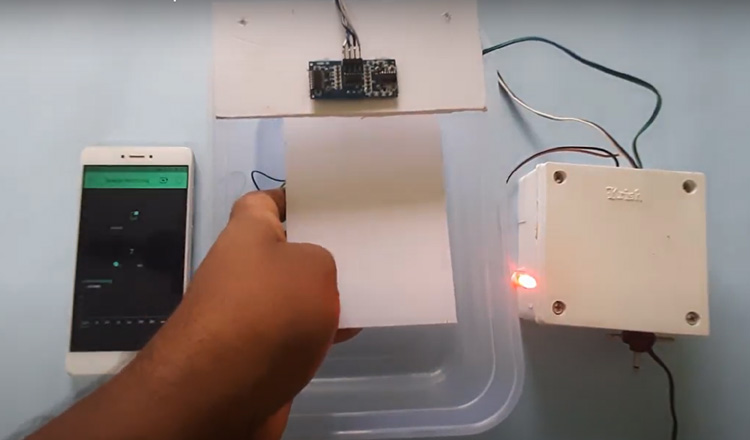
The complete working for this project can be found in the video below, if you have any questions, you can leave them in the comment section below or you can also use our forums.
Complete Project Code
#define BLYNK_PRINT Serial
#include <BlynkSimpleEsp8266.h>
#include <ESP8266WiFi.h>
const int trigPin1 = D3;
const int echoPin1 = D2;
#define redled D4
char auth[]="aX3Cded2oxBxxxxx9bAVEGt1U";
char ssid[] = "admin";
char pass[] = "123456789";
int duration1,distance1;
int count=0;
void setup()
{
  pinMode(trigPin1, OUTPUT);
  pinMode(echoPin1, INPUT);
  pinMode(A0, INPUT);
  digitalWrite(A0, OUTPUT);
  pinMode(redled, OUTPUT);
  digitalWrite(redled, LOW);
  Serial.begin(9600);
  Blynk.begin(auth, ssid, pass);
}
void loop()
{
  int float1=analogRead(A0);
  digitalWrite(trigPin1, LOW);
  delayMicroseconds(2);
  digitalWrite(trigPin1, HIGH);
  delayMicroseconds(10);
  digitalWrite(trigPin1, LOW);
  duration1 = pulseIn(echoPin1, HIGH);
  distance1 = duration1 * 0.034 / 2;
  Serial.println(float1);
   Blynk.virtualWrite(V1,distance1);
   if(distance1<=5)
   {
    Blynk.notify("Blockage Alert!");
    digitalWrite(redled, HIGH);
   }
   else if(float1<=800)
   {
    Blynk.notify("Overflow Alert !");
     digitalWrite(redled, HIGH);
   }
      else
   {
    digitalWrite(redled, LOW);
   }
    Blynk.run();
   }

