Introduction
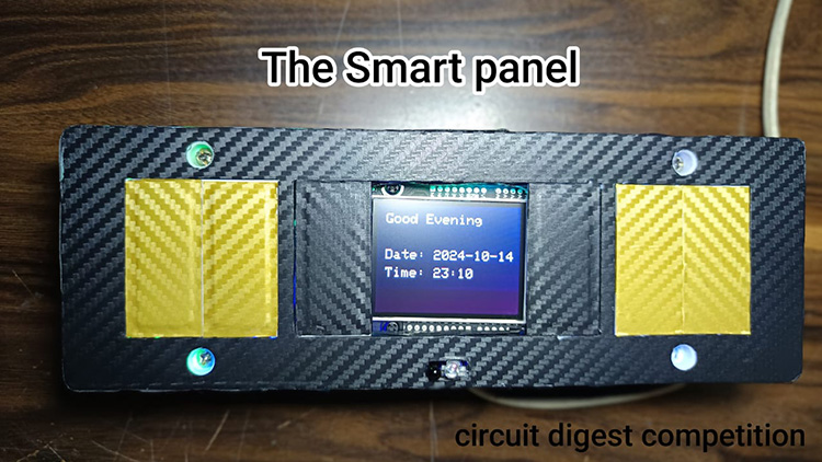
The idea is to use the Sipeed Maxduino Board and an ESP8266 (Nodemcu) With the help of Platform IO and Ardunio Cloud/EspHome. The basics are to attach a four-channel relay and touch sensors hooked up to the NodeMCU board, making it a smart switch unlike other smart switches, which look and feel the same. This switch has some extra features that make it stand out from other switches on the market. This setup has an LED ring that can act as a night light, Notification alert and many more. This device will have a screen (connected to Maixduno) showing the date and time, Room Temperature & humidity. Last but not least when you wave your hand, it greets you and says the time and temperature so you can take things to the next level.
The project uses a 5-volt 20-watt power supply to keep it simple. There are two parts to this project. I will explain this project in two parts. They are as follows
Part-A (Sipeed Maixdunio)
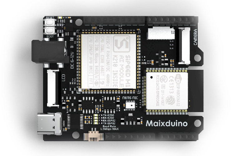
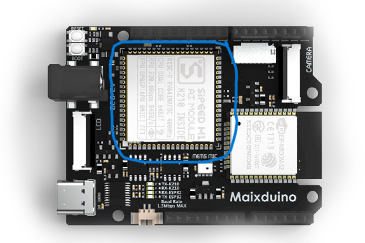
I am using the Sipeed Maxduino AI+IoT Board by Sipeed given by DigiKey, as a primary controller in this project. It will connect to the internet to retrieve the information (Date and Time) displayed on the screen. Also, it will show the Humidty & Temperaure using the Dht11 Sensor.
This part of the circuitry uses the Type C port to power itself and the components.
The components used are
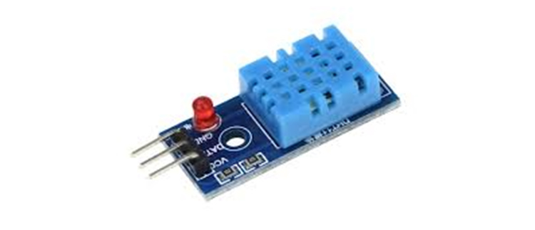
1) DHT11 Sensor - It tells the temperature and humidity of the Room. The Middle pin which is the data pin is connected to the IO4 of the Board
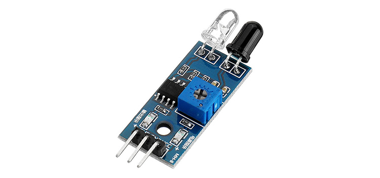
2)Ir Obstacle Sensor - It detects if any person waved their hand in front of the Device. The OUT pin is connected to IO3 of the board
3)Speaker - When the person gets detected it will greet you and tell date and time. It is connected using the dedicated speaker connector
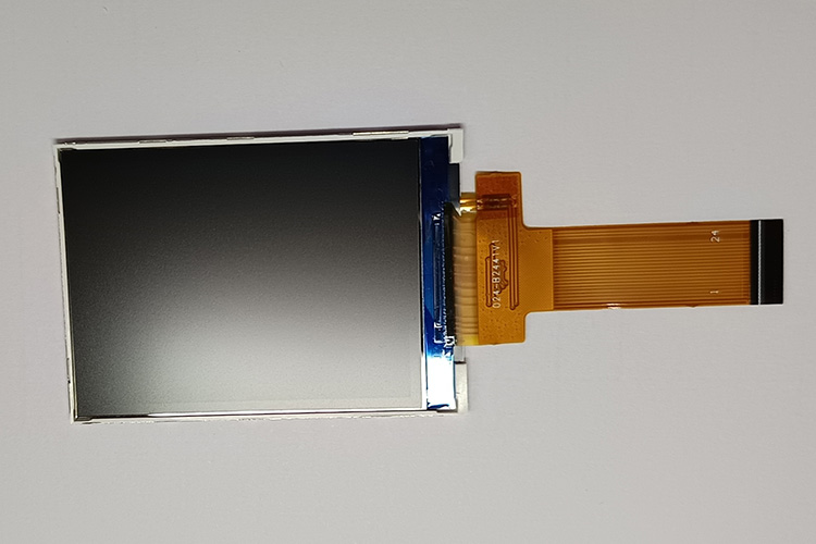
4)Screen - The screen shows the information which is powered by the Sipeed Maixdunio included In the kit from DigiKey
Watch the full demonstration by clicking on the YouTube video below :
CODE EXPLANATION
For coding the board, I have used Platform IO, a Vs Code extension to code the K210 chip. I used it because it is simple to code and upload it to the board with its built-in compiler and uploader
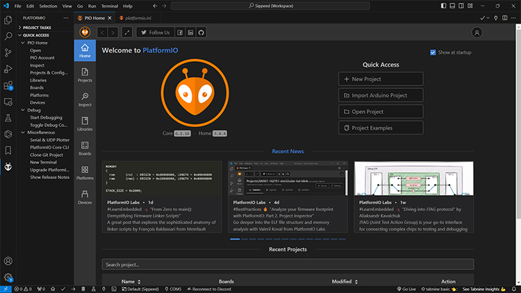
Here is the code for the K210 Chip
#include <Sipeed_ST7789.h> // Library to control the ST7789 LCD display#include <SPI.h> // Library for SPI communication#include <fpioa.h> // K210-specific library for pin mapping#include <gpiohs.h> // K210-specific library for GPIO control#include <uart.h> // K210-specific library for UART communication#include <DHT.h> // Library to control the DHT11 temperature and humidity sensor
// Screen dimensions#define SCREEN_WIDTH 320 // Screen width in pixels#define SCREEN_HEIGHT 240 // Screen height in pixels
// UART configuration#define UART_BAUD 115200 // Baud rate for UART communication
// Pin definitions for the ST7789 LCD#define TFT_CS 10 // Chip select pin for the LCD#define TFT_RST 8 // Reset pin for the LCD#define TFT_DC 9 // Data/Command pin for the LCD#define TFT_MOSI 11 // MOSI (data line) for the LCD#define TFT_CLK 13 // Clock pin for the LCD
// Pin definitions for UART communication between K210 and ESP32#define K210_UART_TX 7 // UART transmit pin on the K210#define K210_UART_RX 6 // UART receive pin on the K210
// Pin definition for the DHT11 sensor#define DHTPIN 4 // Pin where the DHT11 sensor is connected#define DHTTYPE DHT11 // Defining the sensor type as DHT11
// Initializing the DHT sensor objectDHT dht(DHTPIN, DHTTYPE); // Create a DHT object to read temperature and humidity
// Pin for obstacle sensor (hand wave detection)#define OBSTACLE_SENSOR_PIN 3 // Obstacle sensor pin for hand wave detection
// SPI communication setup for LCDSPIClass spi_(SPI0); // Using SPI0 for communicationSipeed_ST7789 lcd(SCREEN_WIDTH, SCREEN_HEIGHT, spi_); // Creating an ST7789 LCD object
// Slide-related variables for managing the display contentint slide = 0; // Variable to track the current slide (0 for time/date, 1 for temp/humidity)unsigned long lastSlideChange = 0; // Timestamp of the last slide changeunsigned long inactiveSlideDuration = 30000; // Time interval for slide change when no activity (30 seconds)unsigned long activeSlideDuration = 5000; // Time interval for slide change when hand wave is detected (5 seconds)unsigned long lastActivityTime = 0; // Last activity timestamp (used to track hand wave detection)int slideCycleCount = 0; // Counter to track the number of slide changesbool handWaveDetected = false; // Flag to indicate if a hand wave was detectedbool colorfulMode = false; // Flag to indicate if "colorful mode" is active (triggered by hand wave)
void setup() {// Initializing SPI communication for the LCDspi_.begin(TFT_CLK, -1, TFT_MOSI, TFT_CS); // Setup SPI communication with the defined pinslcd.begin(15000000); // Initialize LCD with SPI clock speedlcd.setRotation(0); // Set the display rotation (0 for portrait)lcd.fillScreen(COLOR_BLACK); // Clear the screen and fill it with blacklcd.setTextSize(3); // Set the text size for the LCDlcd.setTextColor(COLOR_WHITE); // Set the text color to white
// Configure the UART pins and initialize UART communicationfpioa_set_function(K210_UART_RX, FUNC_UART1_RX); // Set RX pin for UART1fpioa_set_function(K210_UART_TX, FUNC_UART1_TX); // Set TX pin for UART1uart_init(UART_DEVICE_1); // Initialize UART1 deviceuart_config(UART_DEVICE_1, UART_BAUD, UART_BITWIDTH_8BIT, UART_STOP_1, UART_PARITY_NONE); // Configure UART
// Initialize the DHT11 sensordht.begin();
// Configure the obstacle sensor (hand wave detection)fpioa_set_function(OBSTACLE_SENSOR_PIN, FUNC_GPIOHS0); // Map the obstacle sensor pin to GPIOHS0 (high-speed GPIO)gpiohs_set_drive_mode(0, GPIO_DM_INPUT); // Set the obstacle sensor pin as input
// Initialize serial communication for debuggingSerial.begin(115200); // Start serial communication at 115200 baud rateSerial.println("K210 ready for UART communication..."); // Debug message}
// Function to draw a gradient background when displaying timevoid drawDarkerGradientTime() {for (int y = 0; y < SCREEN_HEIGHT; y++) {// Calculate RGB values for the gradientuint8_t r = map(y, 0, SCREEN_HEIGHT, 0x00, 0x40); // Red component (darker)uint8_t g = map(y, 0, SCREEN_HEIGHT, 0x00, 0x00); // Green component (no change)uint8_t b = map(y, 0, SCREEN_HEIGHT, 0x40, 0x20); // Blue component (darker)uint16_t color = ((r & 0xF8) << 8) | ((g & 0xFC) << 3) | (b >> 3); // Convert to 16-bit colorlcd.drawFastHLine(0, y, SCREEN_WIDTH, color); // Draw a horizontal line with the gradient color}}
// Function to draw a gradient background when displaying temperaturevoid drawDarkerGradientTemp() {for (int y = 0; y < SCREEN_HEIGHT; y++) {// Calculate RGB values for the gradient (different from time screen)uint8_t r = map(y, 0, SCREEN_HEIGHT, 0x80, 0xFF); // Red component (brighter)uint8_t g = map(y, 0, SCREEN_HEIGHT, 0x40, 0x00); // Green component (reduces to 0)uint8_t b = map(y, 0, SCREEN_HEIGHT, 0x00, 0x00); // Blue component (stays 0)uint16_t color = ((r & 0xF8) << 8) | ((g & 0xFC) << 3) | (b >> 3); // Convert to 16-bit colorlcd.drawFastHLine(0, y, SCREEN_WIDTH, color); // Draw a horizontal line with the gradient color}}
// Function to clear the screen and fill it with blackvoid drawSolidBlack() {lcd.fillScreen(COLOR_BLACK); // Clear the screen by filling it with black color}
void loop() {unsigned long currentMillis = millis(); // Get the current time (in milliseconds)
// Check if the obstacle sensor detected a hand waveint sensorState = gpiohs_get_pin(0); // Read the state of the obstacle sensorif (sensorState == 1) { // If hand wave detectedhandWaveDetected = true; // Set flag for hand wave detectionlastActivityTime = currentMillis; // Update last activity timestampcolorfulMode = true; // Enable "colorful mode" (active mode)slideCycleCount = 0; // Reset slide cycle counter}
// If no hand wave has been detected for 30 seconds, disable colorful modeif (handWaveDetected && (currentMillis - lastActivityTime >= 30000)) {colorfulMode = false; // Disable colorful mode after 30 seconds of inactivity}
// Set slide interval based on whether colorful mode is active or notunsigned long slideInterval = colorfulMode ? activeSlideDuration : inactiveSlideDuration;
// Check if it's time to switch slidesif (currentMillis - lastSlideChange >= slideInterval) {lastSlideChange = currentMillis; // Update timestamp for slide changeslide = (slide + 1) % 2; // Toggle between slide 0 (time/date) and slide 1 (temp/humidity)}
// Buffer to store incoming UART datachar buffer[128];int available_bytes = uart_receive_data(UART_DEVICE_1, buffer, sizeof(buffer)); // Receive UART data
if (available_bytes > 0) { // If data was receivedbuffer[available_bytes] = ''; // Null-terminate the received stringSerial.print("Received: ");Serial.println((char*)buffer); // Print received data for debugging
String receivedData = String((char*)buffer); // Convert received data to a stringString date = receivedData.substring(0, 10); // Extract date from received dataString time = receivedData.substring(11); // Extract time from received data
// Decide what to display based on the current slide and colorful modeif (colorfulMode) {if (slide == 0) {drawDarkerGradientTime(); // Display time/date with a gradient background} else if (slide == 1) {drawDarkerGradientTemp(); // Display temp/humidity with a gradient background}} else {drawSolidBlack(); // Clear the screen if colorful mode is off}
// Display the time and date on slide 0if (slide == 0) {lcd.setCursor(20, 20); // Set cursor position for the greetingint hour = time.substring(0, 2).toInt(); // Get the current hour// Display a greeting based on the time of dayString greeting = (hour >= 6 && hour < 12) ? "Good Morning" :(hour >= 12 && hour < 18) ? "Good Afternoon" :(hour >= 18 && hour < 24) ? "Good Evening" : "Good Night";
lcd.println(greeting); // Print greeting on the screenlcd.setCursor(20, 100); // Set cursor position for the datelcd.println("Date: " + date); // Print the datelcd.setCursor(20, 140); // Set cursor position for the timelcd.println("Time: " + time); // Print the time}// Display the temperature and humidity on slide 1else if (slide == 1) {float temp = dht.readTemperature(); // Read temperature from DHT11 sensorfloat humidity = dht.readHumidity(); // Read humidity from DHT11 sensorif (isnan(temp) || isnan(humidity)) { // If there's an error reading the sensorlcd.setCursor(20, 50); // Set cursor for error messagelcd.println("Error reading DHT11"); // Print error message} else { // If readings are validlcd.setCursor(20, 50); // Set cursor for temperaturelcd.println("Temp: " + String(temp) + " *C"); // Print temperaturelcd.setCursor(20, 100); // Set cursor for humiditylcd.println("Humidity: " + String(humidity) + "%"); // Print humidity}}}
delay(2000); // Wait for 2 seconds before running the loop again}
Then The Code For The Esp32
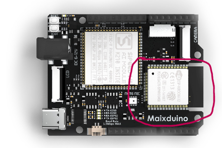
For coding the inbuilt ESP32 on the maixdunio board. I have used Arduino IDE to program it
CODE EXPLANATION
#include <WiFi.h> // Wi-Fi connection library for ESP32#include <WiFiClient.h> // For network client communication#include <NTPClient.h> // For obtaining time from an NTP server#include <WiFiUdp.h> // UDP protocol for NTP communication#include <time.h> // For time manipulation and struct tm
// Define the offset for IST (Indian Standard Time) in seconds (5 hours 30 minutes = 19800 seconds)#define NTP_OFFSET 19800
// Define the interval for updating the time (in milliseconds), here 60 seconds (60000 ms)#define NTP_INTERVAL 60000
// Define the NTP server to get the current time#define NTP_SERVER "pool.ntp.org"
// Wi-Fi credentials (replace with your network details)const char* ssid = "Your SSID"; // Wi-Fi SSIDconst char* password = "Your Password"; // Wi-Fi password
// Create a UDP object for network communicationWiFiUDP udp;
// Create an NTPClient object to communicate with the NTP serverNTPClient timeClient(udp, NTP_SERVER, NTP_OFFSET, NTP_INTERVAL);
void setup() {// Initialize serial communication (UART0) at 115200 baud rate for debuggingSerial.begin(115200);
// Initialize Serial1 (UART1) at 115200 baud rate to send data to other devicesSerial1.begin(115200);
// Start connecting to the Wi-Fi networkWiFi.begin(ssid, password);
// Wait for the ESP32 to connect to the Wi-Fi networkwhile (WiFi.status() != WL_CONNECTED) {delay(500); // Check every 500 ms until connected}
// Start the NTP client to retrieve the current timetimeClient.begin();}
void loop() {// Update the NTP client to fetch the latest time from the servertimeClient.update();
// Get the current epoch time (the number of seconds since January 1, 1970)time_t epochTime = timeClient.getEpochTime();
// Convert the epoch time to a struct tm object containing human-readable timestruct tm* timeinfo = localtime(&epochTime);
// Extract individual components of time and date from the struct tmint hour = timeinfo->tm_hour; // Get the hour (24-hour format)int minute = timeinfo->tm_min; // Get the minutesint second = timeinfo->tm_sec; // Get the secondsint day = timeinfo->tm_mday; // Get the day of the monthint month = timeinfo->tm_mon + 1; // tm_mon is 0-based, so add 1 to get the correct monthint year = timeinfo->tm_year + 1900; // tm_year is years since 1900, so add 1900 to get the full year
// Format the date and time into a string in "YYYY-MM-DD HH:MM:SS" formatString dateTime = String(year) + "-" +(month < 10 ? "0" : "") + String(month) + "-" +(day < 10 ? "0" : "") + String(day) + " " +String(hour) + ":" + (minute < 10 ? "0" : "") + String(minute) + ":" +(second < 10 ? "0" : "") + String(second);
// Print the formatted date and time to the Serial monitor (UART0)Serial.println(dateTime);
// Send the formatted date and time to Serial1 (UART1) for external communicationSerial1.println(dateTime);
// Wait for 2 seconds before repeating the processdelay(2000);}
Part-B
The second controller I use is the ESP8266 (NodeMCU) by Espressif Systems. In the project, it is used as a secondary controller. which only controls the switches and the touch sensors. This board will connect to Ardunio Cloud or Home assistant hub which connects with other IoT devices to make a complete smart home system
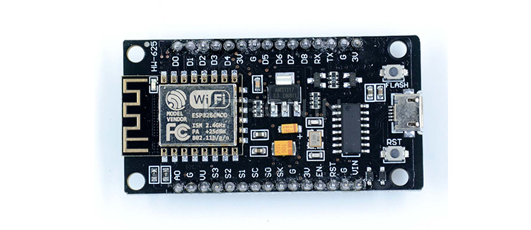
The components are
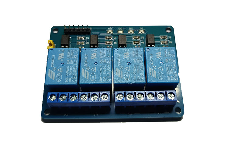
1) 4 Chanel Relay Board - It is an electromagnetic switch that uses a small electric current (here NodeMCU) to control a larger one in this case Lights, Fans etc.
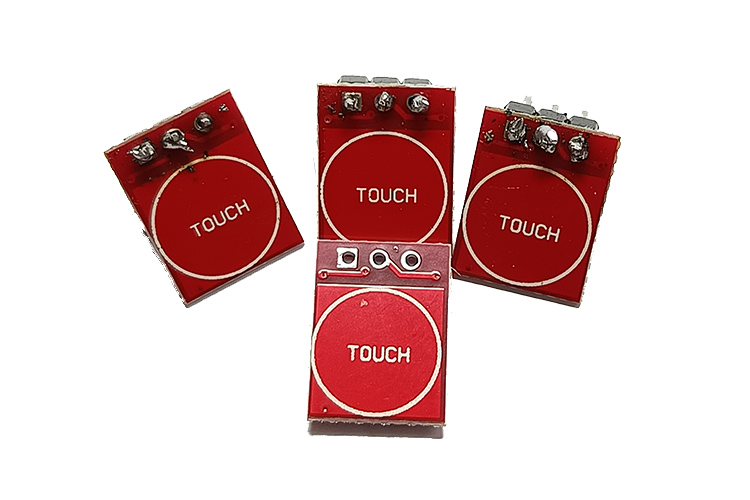
2) TTP223 Touch Sensors - A touch pad detector IC replicates a single tactile button. Here in this project, it's used to control the relay physically (Offline switches)
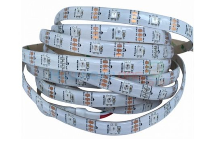
3) WS2812B Led Strips - These are Addressable LED Strips. Where each LED can be controlled individually. Here it is used an LED ring around the devices which makes It look beautiful
CODE EXPLANATION
Here I am using Esphome to control this portion of the devices so that it will work with the other smart home devices flawlessly.
1) ESPhome Setup
esphome:name: smartswitchfriendly_name: SmartSwitch
Defines the name and friendly name of the ESPHome device as "smartswitch."
The friendly name is how it will appear in integrations like Home Assistant
2)ESP8266 Board Setup
esp8266:board: nodemcuv2
Specifies that the microcontroller used is an ESP8266, specifically the "nodemcuv2" variant.
3)Logging
# Enable logging
logger:
Enables logging for debugging and monitoring purposes.
4)Home Assistant API
# Enable Home Assistant APIapi:encryption:key: "LC7R3n3Y7QuWIF3HbxLR6bqhaah33v4YgpvDMMXyf3I="
Enables integration with Home Assistant through the ESPHome API.
The encryption key provides secure communication between the device and Home Assistant.
5)Over-The-Air Updates (OTA)
ota:- platform: esphomepassword: "70dc608e95566662d60e00e9f3284a16"
OTA allows for wireless updates to the device firmware. A password is provided for security.
6)Wi-Fi Configuration
wifissid: !secret wifi_ssidpassword: !secret wifi_password
Connects the device to Wi-Fi using credentials stored in a secrets.yaml file.
Fallback Hotspot
# Enable fallback hotspot (captive portal) in case wifi connection failsap:ssid: "Smartswitch Fallback Hotspot"password: "KzX5Cm9kNAOx"
Creates a fallback access point (AP) in case the Wi-Fi connection fails, allowing you to connect directly to the device.
7)Captive Portal
captive_portal:
Provides a web interface when the fallback hotspot is active.
8) Relay Switch Configuration
switch:- platform: gpiopin: D3 # pin of Relay 1name: Relay1id: relay1inverted: true- platform: gpiopin: D2 # pin of Relay 2name: Relay2id: relay2inverted: true- platform: gpiopin: D1 # pin for Relay 3name: relay3id: relayinverted: true- platform: gpiopin: GPIO10 #Enter pin for Relay 4name: Relay4id: relay4inverted: true
Defines four GPIO-based relays.
inverted:truemeans that the relays are active-low, so sending a low signal activates them.Each relay is given a unique id and a user-friendly name.
9)Touch Sensor Configuration
binary_sensor:- platform: gpiopin: D5 # Enter Touch Sensor 1 pinname: touch_1device_class: windowon_press:- switch.toggle: relay1- platform: gpiopin: D6 # Enter Touch Sensor 2 pinname: touch_2on_press:- switch.toggle: relay2device_class: window- platform: gpiopin: D7 # Enter Touch Sensor 3 pinname: touch_3device_class: windowon_press:- switch.toggle: relay- platform: gpiopin: D8 # Enter Touch Sensor 4 pinname: touch_4device_class: windowon_press:- switch.toggle: relay4
Defines four touch sensors.
Each sensor is mapped to a corresponding relay and toggles the relay when pressed.
device_class:window indicates the type of binary sensor (typically used for windows or doors but customizable here).
10)NeoPixel Light Strip
light:- platform: neopixelbustype: GRBvariant: ws2811pin: D0 # Led Light Strips pinnum_leds: 16name: "NeoPixel Light"effects:- pulse:- pulse:name: "Fast Pulse"transition_length: 0.5supdate_interval: 0.5smin_brightness: 0%max_brightness: 100%
- addressable_rainbow:- addressable_rainbow:name: Rainbow Effect (Cv)speed: 10width: 50
- addressable_fireworks:- addressable_fireworks:name: Fireworks Effect (Random Color)update_interval: 32msspark_probability: 10%use_random_color: Truefade_out_rate: 120
- addressable_scan:name: Scan Effect (cV)move_interval: 100msscan_width: 1- addressable_color_wipe:- addressable_color_wipe:name: Color Wipe Effect (CV)colors:- red: 100%green: 100%blue: 100%num_leds: 1- red: 0%green: 0%blue: 0%num_leds: 1add_led_interval: 100msreverse: false
Configures a NeoPixel (WS2811) light strip with 16 LEDs, controlled via pin D0.
Provides various lighting effects, including pulse, rainbow, fireworks, scan, and colour wipe.
Each effect can be customized with parameters such as speed, brightness, and transition time.
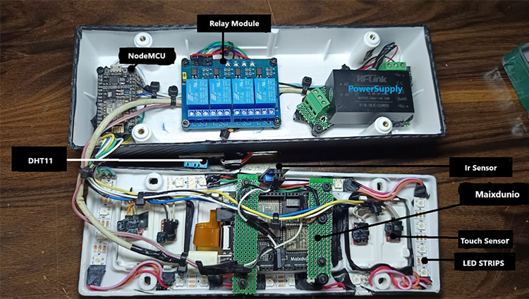
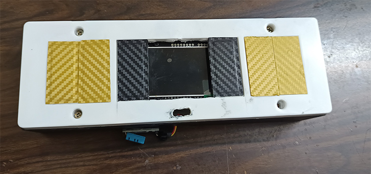
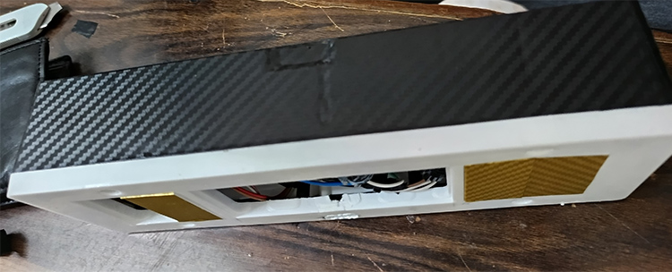
Internals Of The Panel
Here you can see the image of all the components put together
Key Features Of My Project
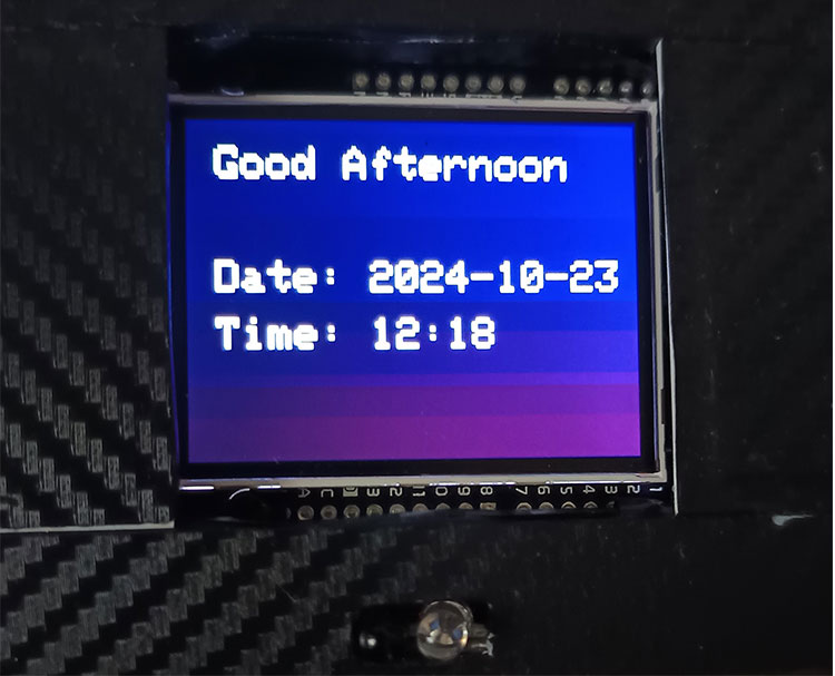
The Greeting Screen
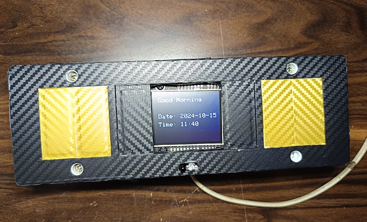
Here you can see the welcome screen which shows "Good Morning", "Good Afternoon", "Good Evening " or "Good Night" according to the Time. Below is the Date in the format YYYY:MM:DD Then the Last is the Time which shows in the format HH:MM
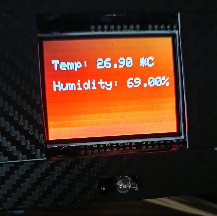
The next slide is Temperature and Humidity, which first shows the Temperature in Celsius and Below it displays the Humidity in %
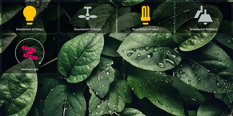
The Dashboard
Here you can see the Dashboard where I can control the switches and the LED ring
The Led Ring
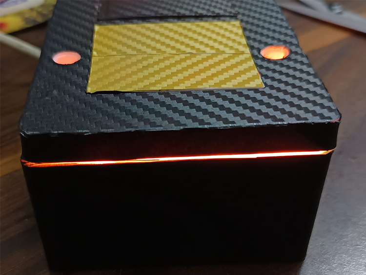
Here you can see the Led Ring in action. we can automate it to do things like when someone rings the doorbell, it flashes to notify you
The Appearance
Unlike Other Switched I didn't want it to look plain so I vinyl-wrapped it with a golden colour carbon fibre pattern for the switches and Black carbon fibre for the rest of the body.
Circuit Diagram of Part A- Sipeed Maixdunio
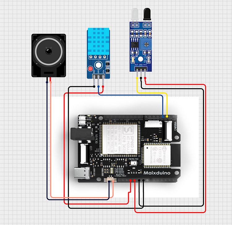
Circuit Diagram of Part B-ESP8266
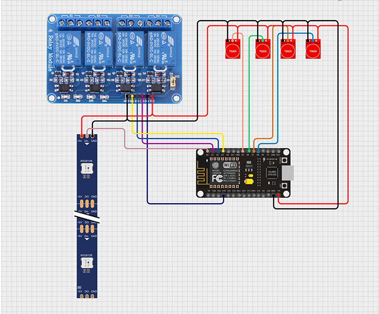
See the project's complete code and schematics on GitHub.
Complete Project Code
#include <Sipeed_ST7789.h>
#include <SPI.h>
#include <fpioa.h>
#include <gpiohs.h>
#include <uart.h>
#include <DHT.h>
#define SCREEN_WIDTH 320
#define SCREEN_HEIGHT 240
#define UART_BAUD 115200
#define TFT_CS   10
#define TFT_RST  8
#define TFT_DC   9
#define TFT_MOSI 11
#define TFT_CLK  13
#define K210_UART_TX 7
#define K210_UART_RX 6
#define DHTPIN 4
#define DHTTYPE DHT11
DHT dht(DHTPIN, DHTTYPE);
#define OBSTACLE_SENSOR_PIN 3
SPIClass spi_(SPI0);
Sipeed_ST7789 lcd(SCREEN_WIDTH, SCREEN_HEIGHT, spi_);
int slide = 0;
unsigned long lastSlideChange = 0;
unsigned long inactiveSlideDuration = 30000;
unsigned long activeSlideDuration = 5000;
unsigned long lastActivityTime = 0;
int slideCycleCount = 0;
bool handWaveDetected = false;
bool colorfulMode = false;
void setup() {
   spi_.begin(TFT_CLK, -1, TFT_MOSI, TFT_CS);
   lcd.begin(15000000);
   lcd.setRotation(0);
   lcd.fillScreen(COLOR_BLACK);
   lcd.setTextSize(3);
   lcd.setTextColor(COLOR_WHITE);
   fpioa_set_function(K210_UART_RX, FUNC_UART1_RX);
   fpioa_set_function(K210_UART_TX, FUNC_UART1_TX);
   uart_init(UART_DEVICE_1);
   uart_config(UART_DEVICE_1, UART_BAUD, UART_BITWIDTH_8BIT, UART_STOP_1, UART_PARITY_NONE);
   dht.begin();
   fpioa_set_function(OBSTACLE_SENSOR_PIN, FUNC_GPIOHS0);
   gpiohs_set_drive_mode(0, GPIO_DM_INPUT);
   Serial.begin(115200);
   Serial.println("K210 ready for UART communication...");
}
void drawDarkerGradientTime() {
   for (int y = 0; y < SCREEN_HEIGHT; y++) {
       uint8_t r = map(y, 0, SCREEN_HEIGHT, 0x00, 0x40);
       uint8_t g = map(y, 0, SCREEN_HEIGHT, 0x00, 0x00);
       uint8_t b = map(y, 0, SCREEN_HEIGHT, 0x40, 0x20);
       uint16_t color = ((r & 0xF8) << 8) | ((g & 0xFC) << 3) | (b >> 3);
       lcd.drawFastHLine(0, y, SCREEN_WIDTH, color);
   }
}
void drawDarkerGradientTemp() {
   for (int y = 0; y < SCREEN_HEIGHT; y++) {
       uint8_t r = map(y, 0, SCREEN_HEIGHT, 0x80, 0xFF);
       uint8_t g = map(y, 0, SCREEN_HEIGHT, 0x40, 0x00);
       uint8_t b = map(y, 0, SCREEN_HEIGHT, 0x00, 0x00);
       uint16_t color = ((r & 0xF8) << 8) | ((g & 0xFC) << 3) | (b >> 3);
       lcd.drawFastHLine(0, y, SCREEN_WIDTH, color);
   }
}
void drawSolidBlack() {
   lcd.fillScreen(COLOR_BLACK);
}
void loop() {
   unsigned long currentMillis = millis();
   int sensorState = gpiohs_get_pin(0);
   if (sensorState == 1) {
       handWaveDetected = true;
       lastActivityTime = currentMillis;
       colorfulMode = true;
       slideCycleCount = 0;
   }
   if (handWaveDetected && (currentMillis - lastActivityTime >= 30000)) {
       colorfulMode = false;
   }
   unsigned long slideInterval = colorfulMode ? activeSlideDuration : inactiveSlideDuration;
   if (currentMillis - lastSlideChange >= slideInterval) {
       lastSlideChange = currentMillis;
       slide = (slide + 1) % 2;
   }
   char buffer[128];
   int available_bytes = uart_receive_data(UART_DEVICE_1, buffer, sizeof(buffer));
   if (available_bytes > 0) {
       buffer[available_bytes] = '';
       Serial.print("Received: ");
       Serial.println((char*)buffer);
       String receivedData = String((char*)buffer);
       String date = receivedData.substring(0, 10);
       String time = receivedData.substring(11);
       if (colorfulMode) {
           if (slide == 0) {
               drawDarkerGradientTime();
           } else if (slide == 1) {
               drawDarkerGradientTemp();
           }
       } else {
           drawSolidBlack();
       }
       if (slide == 0) {
           lcd.setCursor(20, 20);
           int hour = time.substring(0, 2).toInt();
           String greeting = (hour >= 6 && hour < 12) ? "Good Morning" :
                             (hour >= 12 && hour < 18) ? "Good Afternoon" :
                             (hour >= 18 && hour < 24) ? "Good Evening" : "Good Night";
           lcd.println(greeting);
           lcd.setCursor(20, 100);
           lcd.println("Date: " + date);
           lcd.setCursor(20, 140);
           lcd.println("Time: " + time);
       } else if (slide == 1) {
           float temp = dht.readTemperature();
           float humidity = dht.readHumidity();
           if (isnan(temp) || isnan(humidity)) {
               lcd.setCursor(20, 50);
               lcd.println("Error reading DHT11");
           } else {
               lcd.setCursor(20, 50);
               lcd.println("Temp: " + String(temp) + " *C");
               lcd.setCursor(20, 100);
               lcd.println("Humidity: " + String(humidity) + "%");
           }
       }
   }
   delay(2000);
}
#include <WiFi.h>
#include <WiFiClient.h>
#include <NTPClient.h>
#include <WiFiUdp.h>
#include <time.h>  // Include this for time functions
#define NTP_OFFSET 19800
#define NTP_INTERVAL 60000
#defineNTP_SERVER"pool.ntp.org"
const char* ssid = "Your SSID";
const char* password = "Your Password";
WiFiUDP udp;
NTPClient timeClient(udp, NTP_SERVER, NTP_OFFSET, NTP_INTERVAL);
void setup() {
 Serial.begin(115200);
 Serial1.begin(115200);
 WiFi.begin(ssid, password);
 while (WiFi.status() != WL_CONNECTED) {
   delay(500);
 }
 timeClient.begin();
}
void loop() {
 timeClient.update();
 time_t epochTime = timeClient.getEpochTime();  // Store as time_t
 struct tm* timeinfo = localtime(&epochTime);    // Convert to struct tm
 // Extract date and time from the struct tm
 int hour = timeinfo->tm_hour;
 int minute = timeinfo->tm_min;
 int second = timeinfo->tm_sec;
 int day = timeinfo->tm_mday;
 int month = timeinfo->tm_mon + 1; // tm_mon is 0-based
 int year = timeinfo->tm_year + 1900; // tm_year is years since 1900
 String dateTime = String(year) + "-" + (month < 10 ? "0" : "") + String(month) + "-" +
                   (day < 10 ? "0" : "") + String(day) + " " +
                   String(hour) + ":" + (minute < 10 ? "0" : "") + String(minute) + ":" +
                   (second < 10 ? "0" : "") + String(second);
 Serial.println(dateTime);
 Serial1.println(dateTime);
 delay(2000);
}
esphome:
name: smartswitch
friendly_name: SmartSwitch
esp8266:
board: nodemcuv2
# Enable logging
logger:
# Enable Home Assistant API
api:
encryption:
key: "LC7R3n3Y7QuWIF3HbxLR6bqhaah33v4YgpvDMMXyf3I="
ota:
- platform: esphome
password: "70dc608e95566662d60e00e9f3284a16"
wifi:
ssid: !secret wifi_ssid
password: !secret wifi_password
# Enable fallback hotspot (captive portal) in case wifi connection fails
ap:
ssid: "Smartswitch Fallback Hotspot"
password: "KzX5Cm9kNAOx"
captive_portal:
switch:
- platform: gpio
pin: D3 #Enter pin for Relay 1
name: Relay1
id: relay1
inverted: true
- platform: gpio
pin: D2 #Enter pin for Relay 2
name: Relay2
id: relay2
inverted: true
- platform: gpio
pin: D1 #Enter pin for Relay 3
name: relay3
id: relay
inverted: true
- platform: gpio
pin: GPIO10 #Enter pin for Relay 4
name: Relay4
id: relay4
inverted: true
binary_sensor:
- platform: gpio
pin: D5 # Enter Touch Sensor 1 pin
name: touch_1
device_class: window
on_press:
- switch.toggle: relay1
- platform: gpio
pin: D6 # Enter Touch Sensor 2 pin
name: touch_2
on_press:
- switch.toggle: relay2
device_class: window
- platform: gpio
pin: D7 # Enter Touch Sensor 3 pin
name: touch_3
device_class: window
on_press:
- switch.toggle: relay
- platform: gpio
pin: D8 # Enter Touch Sensor 4 pin
name: touch_4
device_class: window
on_press:
- switch.toggle: relay4
light:
- platform: neopixelbus
type: GRB
variant: ws2811
pin: D0 #Enter LedStrips pin
num_leds: 16
name: "NeoPixel Light"
effects:
- pulse:
- pulse:
name: "Fast Pulse"
transition_length: 0.5s
update_interval: 0.5s
min_brightness: 0%
max_brightness: 100%
- addressable_rainbow:
- addressable_rainbow:
name: Rainbow Effect (Cv)
speed: 10
width: 50
- addressable_fireworks:
- addressable_fireworks:
name: Fireworks Effect (Random Color)
update_interval: 32ms
spark_probability: 10%
use_random_color: True
fade_out_rate: 120
- addressable_scan:
name: Scan Effect (cV)
move_interval: 100ms
scan_width: 1
- addressable_color_wipe:
- addressable_color_wipe:
name: Color Wipe Effect (CV)
colors:
- red: 100%
green: 100%
blue: 100%
num_leds: 1
- red: 0%
green: 0%
blue: 0%
num_leds: 1
add_led_interval: 100ms
reverse: false


