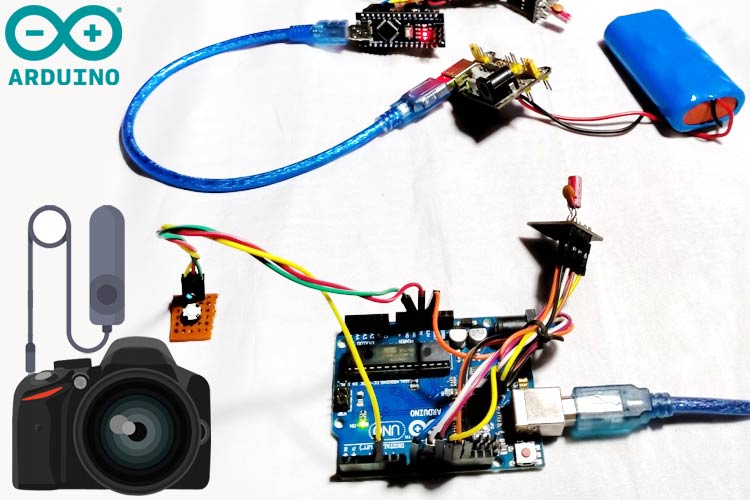
Who does not love photography! There are lots of subjects in this creative field and each one is unique, let's choose one. How much all of us love to see wild animals on National Geography or Discovery channels? Yes, I am talking about one of the widely cultivated genres of photography as well as one of the most dangerous photography subjects that is Wildlife Photography. In Wildlife Photography, there are situations where getting close to the subject may become life-threatening or dangerous, but at the same time, the photo needs to be captured. In such a case, a wired switch that could control the camera from a long distance will be beneficial in such cases. What if it goes wireless? It will definitely be of great benefit for the photographer.
Here, in this project, we will build a wireless controlled shutter button for the DSLR. To do that, we will be using the nRF24L01–2.4GHz RF Transceiver module with Arduino UNO, so there is no need to be present with the DSLR camera, and it can be triggered far from the sight. We previously used nRF24L01 with Arduino to control the servo motor and create a Chat Room.
Components Required to Build Wireless Trigger for DSLR
Since this project deals with wireless control, a wireless receiver or transmitter is required. That is none other than NRF24L01 pairs. By using this with a microcontroller, data transfer can be done wirelessly. We used Arduino UNO and Arduino NANO for this one.
- Arduino UNO Board
- USB Cable with 5V Adapter or Power Bank - 2 Pcs
- Arduino NANO
- NRF24L01 - 2pcs
- 2.5mm JACK - Monotype.
- 5V converter (Requires if it is using 7.4V Lithium Battery)
DSLR Remote Trigger - Schematic Diagram
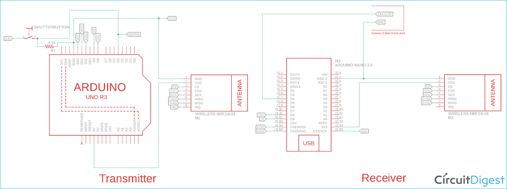
Schematic Diagram to build remote trigger for DSLR is shown below.
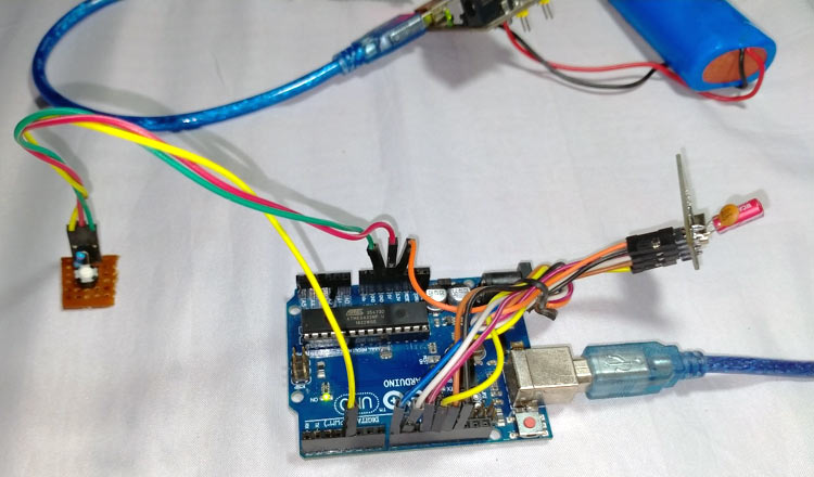
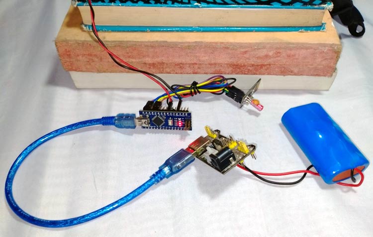
The Schematic is simple and is divided into two sections, nRF24L01 with Arduino to act as Receiver and nRF24L01 with Arduino to act as Transmitter. In the receiver section, the button is in a low state, thus a pull-down resistor is used. When the button is pressed, it will make the pin D4 as Low to High. This data will be transmitted via nRF24L01. On the other hand, the Receiver will receive the data and transfer this to the 2.5mm Jack. Both the transmitter and receiver circuit setup are shown below.
Explanation of the Circuit and Working
DSLR supports shutter remote input where existing wired remotes can be connected to trigger the shutter. This can be seen in the image given below.
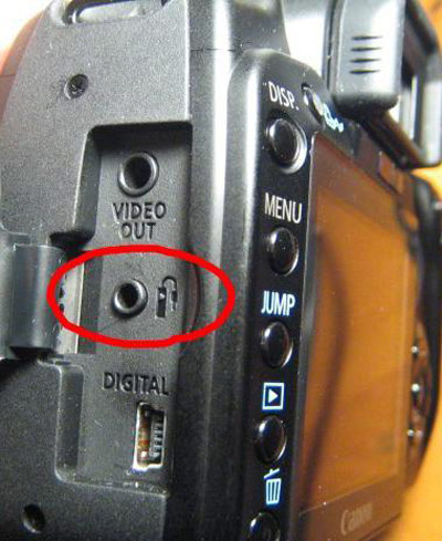
The connection of this pin can be seen in the image given below.
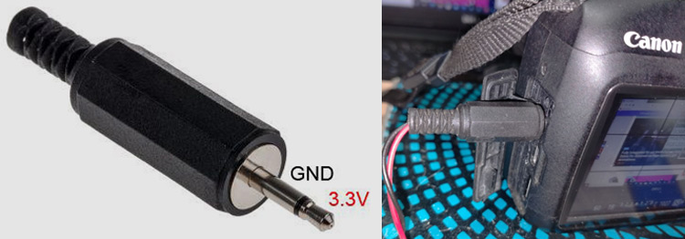
The tip is connected with the shutter button internally in the DSLR. It is in 3.3V level by using a pull-up resistor available inside of the 2.5mm Jack. Now, when this tip gets 0V or Low, the shutter button gets released. This is done using the Arduino NANO. Whenever the Arduino Nano receives the data via NRF24L01 that the switch in the transmitter is pressed, it immediately makes the TIP of the connector to Low.
On the other hand, there is a pull-up resistor used across the Arduino UNO. Whenever the switch is pressed, the input pin where the switch is connected gets low. The Arduino further transmits this data via nRF24L01 to the transmitter. Also, the button on the transmitter side uses a debounce for false triggering issues. Another important module is the NRF24L201. This is used as a pair. Below is the pin diagram of NRF24L01.

It can be configured as a Receiver or as a Transmitter. It is a very low-cost RF transceiver module that uses 2.4GHz of RF range and could produce a very long range of data transmission from 50 feet to 200 feet of distance. To know how this can be configured, let's move into the code. To understand the work, kindly look into the code comments as well as the descriptions. Previously, we have dedicated an article on the communication process of NRF modules where we have mentioned all the necessary things to abort this module, you can check that out if you want to know more about these modules.
Arduino Code for Remote DSLR Trigger
There are two different codes used for this project, one for the Transmitter and the other one for the Receiver.
Code For the Transmitter:
The Libraries are included first.
//Include Libraries
#include <SPI.h>
#include <nRF24L01.h>
#include <RF24.h>
#include "printf.h"
#include <ArduinoJson.h>
The address is set, This must be the same for both transmitter and receiver.
//address through which two modules communicate.
const byte address[6] = {0xe1, 0xe1, 0xe1, 0xe1, 0xe1};
A boolean is created where the trigger state will be changed from true to false or vice versa.
volatile bool isTrigger = false;
The next step is to start the NRF24L01 before running the actual application. Here, the range, data type, and state are also set. The nRF24L01 is set as a transmitter, and it is also set for the long-range distance with maximum RF Power. Also, put the address that was previously set.
void setup()
{
  Serial.begin(9600);
  printf_begin();
  Serial.println(F("\n\rRF24/examples/scanner/"));
  // Setup and configure rf radio
  radio.begin();
  radio.setAutoAck(false);
  //set the address
  radio.openWritingPipe(address);
  radio.setPALevel(RF24_PA_MIN); //set as: RF24_PA_MIN, RF24_PA_LOW, RF24_PA_HIGH, RF24_PA_MAX
  radio.setDataRate(RF24_2MBPS); //set as: F24_250KBPS, F24_1MBPS, F24_2MBPS ==>250KBPS = longest range
  radio.setChannel(115); //sets channel from 2.4 to 2.524 GHz in 1 MHz increments 2.483.5 GHz is normal legal limit
  radio.setCRCLength(RF24_CRC_8);
  //  radio.printDetails();
  //Set module as transmitter
  radio.stopListening();
After setting the Transmitter nRF24L01, it is time to set the button input that will be pressed by the user during the trigger. The pin is set as input mode.
  pinMode(SHUTT_REMOTE_TRIGGER_PIN, INPUT);   // sets the digital pin "SHUTT_TRIGGER_PIN" as output
  //  attachInterrupt(digitalPinToInterrupt(SHUTT_REMOTE_TRIGGER_PIN), shutter_remote_trigger, LOW);
  //  attachInterrupt(digitalPinToInterrupt(SHUTT_REMOTE_TRIGGER_PIN), shutter_remote_trigger, HIGH  );
}
void shutter_remote_trigger() {
  isTrigger = true;
}
// Variables will change:
int ledState = HIGH; // the current state of the output pin
int buttonState;   // the current reading from the input pin
int lastButtonState = LOW;   // the previous reading from the input pin
// the following variables are unsigned longs because the time, measured in
// milliseconds will quickly become a bigger number than can be stored in an int.
unsigned long lastDebounceTime = 0; // the last time the output pin was toggled
unsigned long debounceDelay = 50; // the debounce time; increase if the output flickers
In the loop, the button state is constantly monitored and whenever it is pressed, a JSON is sent to the receiver.
void loop()
{
 // read the state of the switch into a local variable:
  int reading = digitalRead(SHUTT_REMOTE_TRIGGER_PIN);
  // check to see if you just pressed the button
  // (i.e. the input went from LOW to HIGH), and you've waited long enough
  // since the last press to ignore any noise:
  // If the switch changed, due to noise or pressing:
  if (reading != lastButtonState) {
                // reset the debouncing timer
                lastDebounceTime = millis();
  }
  if ((millis() - lastDebounceTime) > debounceDelay) {
                // whatever the reading is at, it's been there for longer than the debounce
                // delay, so take it as the actual current state:
                // if the button state has changed:
                if (reading != buttonState) {
                buttonState = reading;
                // only toggle the LED if the new button state is LOW
                if (buttonState == LOW) {
                isTrigger = true;
                }
                }
  }
  // save the reading. Next time through the loop, it'll be the lastButtonState:
  lastButtonState = reading;
  if (true == isTrigger) {
                // Allocate the JSON document
                //
                // Inside the brackets, 200 is the RAM allocated to this document.
                // Don't forget to change this value to match your requirement.
                // Use arduinojson.org/v6/assistant to compute the capacity.
                StaticJsonDocument<50> doc;
                doc[SHUTT_TRIGGER_JSON_KEY] = SHUTT_TRIGGER_ACTIVE;
                //Send message to receiver
                char send_dt[32] = {0};
                String output;
                //serializeJson(doc, Serial);
                serializeJson(doc, send_dt);
                Serial.println(send_dt);
                radio.write(&send_dt, sizeof(send_dt));
                isTrigger = false;
  }
  delay(10);
}
Code For the Receiver:
This code is similar to the transmitter, but after receiving the bit, it provides data for the trigger.
The Libraries are included first.
//Include Libraries
#include <SPI.h>
#include <nRF24L01.h>
#include <RF24.h>
#include "printf.h"
#include <ArduinoJson.h>
The address is set, as discussed before, this address must be the same for both transmitter and receiver. It is given previously in the transmitter address section as well.
//address through which two modules communicate.
const byte address[6] = {0xe1, 0xe1, 0xe1, 0xe1, 0xe1};
The next step is to start the nRF24L01 before running the actual application. Here, the range, data type, and the state are also set the same as the transmitter section, but here it is set as a receiver instead of a transmitter. It is also set for the long-range distance with maximum RF Power.
It also puts the address that was previously set.
void setup()
{
  Serial.begin(9600);
  printf_begin();
  //Serial.println(F("\n\rRF24/examples/scanner/"));
  // Setup and configure rf radio
  radio.begin();
  radio.setAutoAck(false);
  radio.openReadingPipe(0, address);
  radio.setPALevel(RF24_PA_MIN); //set as: RF24_PA_MIN, RF24_PA_LOW, RF24_PA_HIGH, RF24_PA_MAX
  radio.setDataRate(RF24_2MBPS); //set as: F24_250KBPS, F24_1MBPS, F24_2MBPS ==>250KBPS = longest range
  radio.setChannel(115); //sets channel from 2.4 to 2.524 GHz in 1 MHz increments 2.483.5 GHz is normal legal limit
  radio.setCRCLength(RF24_CRC_8);
  // Get into standby mode
  radio.startListening();
After setting the Receiver nRF24L01, it is time to put the logic to set the shutter pin low if the JSON is received that has the information of the button being pressed.
void loop()
{
  digitalWrite(SHUTT_TRIGGER_PIN, HIGH);
  //Read the data if available in buffer
  if (radio.available())
  {
                // Allocate the JSON document
                //
                // Inside the brackets, 200 is the capacity of the memory pool in bytes.
                // Don't forget to change this value to match your JSON document.
                // Use arduinojson.org/v6/assistant to compute the capacity.
                StaticJsonDocument<50> doc;
                char recv_dt[32] = {0};
                radio.read(&recv_dt, sizeof(recv_dt));
                Serial.println(recv_dt);
                // Deserialize the JSON document
                DeserializationError error = deserializeJson(doc, recv_dt);
                // Test if parsing succeeds.
                if (error) {
                Serial.print(F("deserializeJson() failed: "));
                Serial.println(error.f_str());
                //return;
                } else {
                // Fetch values.
                //
                // Most of the time, you can rely on the implicit casts.
                // In other case, you can do doc["time"].as<long>();
                char s_trig_stat = doc[SHUTT_TRIGGER_JSON_KEY];
                if (SHUTT_TRIGGER_ACTIVE == s_trig_stat) {
                Serial.println("Set Shutter pin Low");
                digitalWrite(SHUTT_TRIGGER_PIN, LOW); // sets the digital pin "SHUTT_TRIGGER_PIN" on
                digitalWrite(LED_BUILTIN, HIGH);
                delay(250);  // waits for a 250 millisecond
                }
                }
                digitalWrite(LED_BUILTIN, LOW);
  }
}
Testing
To test the circuit, the transmitter and receiver circuit is constructed properly. A 2.5mm mono jack is used with the DSLR and tested for the circuitry operations.
Below are the images of the setup.
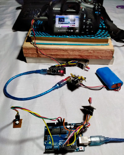
To check the full testing and working, please watch the video given below. And if you have any questions regarding this project, feel free to comment down below.
Complete Project Code
Transmitter Code:
//Include Libraries

#include <SPI.h>

#include <nRF24L01.h>

#include <RF24.h>

#include "printf.h"

#include <ArduinoJson.h>

//create an RF24 object

RF24 radio(9, 8);  // CE, CSN

//address through which two modules communicate.

const byte address[6] = {0xe1, 0xe1, 0xe1, 0xe1, 0xe1};

//DSLR Shutter Trigger Operation's variable

#define SHUTT_TRIGGER_JSON_KEY  "s_trig"

#define SHUTT_TRIGGER_ACTIVE 100

#define SHUTT_TRIGGER_INACTIVE 0

#define SHUTT_REMOTE_TRIGGER_PIN 4

volatile bool isTrigger = false;

void setup()

{

  Serial.begin(9600);

  printf_begin();

  Serial.println(F("\n\rRF24/examples/scanner/"));

  // Setup and configure rf radio

  radio.begin();

  radio.setAutoAck(false);

  //set the address

  radio.openWritingPipe(address);

  radio.setPALevel(RF24_PA_MIN); //set as: RF24_PA_MIN, RF24_PA_LOW, RF24_PA_HIGH, RF24_PA_MAX

  radio.setDataRate(RF24_2MBPS); //set as: F24_250KBPS, F24_1MBPS, F24_2MBPS ==>250KBPS = longest range

  radio.setChannel(115); //sets channel from 2.4 to 2.524 GHz in 1 MHz increments 2.483.5 GHz is normal legal limit

  radio.setCRCLength(RF24_CRC_8);

  //  radio.printDetails();

  //Set module as transmitter

  radio.stopListening();

  pinMode(SHUTT_REMOTE_TRIGGER_PIN, INPUT);      // sets the digital pin "SHUTT_TRIGGER_PIN" as output

  //  attachInterrupt(digitalPinToInterrupt(SHUTT_REMOTE_TRIGGER_PIN), shutter_remote_trigger, LOW);

  //  attachInterrupt(digitalPinToInterrupt(SHUTT_REMOTE_TRIGGER_PIN), shutter_remote_trigger, HIGH  );

}

void shutter_remote_trigger() {

  isTrigger = true;

}

// Variables will change:

int ledState = HIGH;               // the current state of the output pin

int buttonState;            // the current reading from the input pin

int lastButtonState = LOW;   // the previous reading from the input pin
// the following variables are unsigned longs because the time, measured in

// milliseconds will quickly become a bigger number than can be stored in an int.

unsigned long lastDebounceTime = 0;  // the last time the output pin was toggled

unsigned long debounceDelay = 50;  // the debounce time; increase if the output flickers

void loop()

{

  // read the state of the switch into a local variable:

  int reading = digitalRead(SHUTT_REMOTE_TRIGGER_PIN);

  // check to see if you just pressed the button

  // (i.e. the input went from LOW to HIGH), and you've waited long enough

  // since the last press to ignore any noise:

  // If the switch changed, due to noise or pressing:

  if (reading != lastButtonState) {

            // reset the debouncing timer

            lastDebounceTime = millis();

  }

  if ((millis() - lastDebounceTime) > debounceDelay) {

            // whatever the reading is at, it's been there for longer than the debounce

            // delay, so take it as the actual current state:
            // if the button state has changed:

            if (reading != buttonState) {

            buttonState = reading;

            // only toggle the LED if the new button state is LOW

            if (buttonState == LOW) {

            isTrigger = true;

            }

            }

  }

  // save the reading. Next time through the loop, it'll be the lastButtonState:

  lastButtonState = reading;

  if (true == isTrigger) {

            // Allocate the JSON document

            //

            // Inside the brackets, 200 is the RAM allocated to this document.

            // Don't forget to change this value to match your requirement.

            // Use arduinojson.org/v6/assistant to compute the capacity.

            StaticJsonDocument<50> doc;

            doc[SHUTT_TRIGGER_JSON_KEY] = SHUTT_TRIGGER_ACTIVE;

            //Send message to receiver

            char send_dt[32] = {0};

            String output;

            //serializeJson(doc, Serial);

            serializeJson(doc, send_dt);

            Serial.println(send_dt);

            radio.write(&send_dt, sizeof(send_dt));

            isTrigger = false;

  }

  delay(10);

}

Receiver Code -

//Include Libraries

#include <SPI.h>

#include <nRF24L01.h>

#include <RF24.h>

#include "printf.h"

#include <ArduinoJson.h>

//create an RF24 object

RF24 radio(9, 8);  // CE, CSN

//address through which two modules communicate.

const byte address[6] = {0xe1, 0xe1, 0xe1, 0xe1, 0xe1};

//DSLR Shutter Trigger Operation's variable

#define SHUTT_TRIGGER_JSON_KEY  "s_trig"

#define SHUTT_TRIGGER_ACTIVE 100

#define SHUTT_TRIGGER_INACTIVE 0

#define SHUTT_TRIGGER_PIN 4

void setup()

{

  Serial.begin(9600);

  printf_begin();

  //Serial.println(F("\n\rRF24/examples/scanner/"));

  // Setup and configure rf radio

  radio.begin();

  radio.setAutoAck(false);

  radio.openReadingPipe(0, address);

  radio.setPALevel(RF24_PA_MIN); //set as: RF24_PA_MIN, RF24_PA_LOW, RF24_PA_HIGH, RF24_PA_MAX

  radio.setDataRate(RF24_2MBPS); //set as: F24_250KBPS, F24_1MBPS, F24_2MBPS ==>250KBPS = longest range

  radio.setChannel(115); //sets channel from 2.4 to 2.524 GHz in 1 MHz increments 2.483.5 GHz is normal legal limit

  radio.setCRCLength(RF24_CRC_8);

  // Get into standby mode

  radio.startListening();

  pinMode(LED_BUILTIN, OUTPUT);

  pinMode(SHUTT_TRIGGER_PIN, OUTPUT);       // sets the digital pin "SHUTT_TRIGGER_PIN" as output

  digitalWrite(SHUTT_TRIGGER_PIN, HIGH);  // sets the digital pin "SHUTT_TRIGGER_PIN" off

}

void loop()

{

  digitalWrite(SHUTT_TRIGGER_PIN, HIGH);

  //Read the data if available in buffer

  if (radio.available())

  {

            // Allocate the JSON document

            //

            // Inside the brackets, 200 is the capacity of the memory pool in bytes.

            // Don't forget to change this value to match your JSON document.

            // Use arduinojson.org/v6/assistant to compute the capacity.

            StaticJsonDocument<50> doc;

            char recv_dt[32] = {0};

            radio.read(&recv_dt, sizeof(recv_dt));

            Serial.println(recv_dt);

            // Deserialize the JSON document

            DeserializationError error = deserializeJson(doc, recv_dt);

            // Test if parsing succeeds.

            if (error) {

            Serial.print(F("deserializeJson() failed: "));

            Serial.println(error.f_str());

            //return;

            } else {

            // Fetch values.

            //

            // Most of the time, you can rely on the implicit casts.

            // In other case, you can do doc["time"].as<long>();

            char s_trig_stat = doc[SHUTT_TRIGGER_JSON_KEY];

            if (SHUTT_TRIGGER_ACTIVE == s_trig_stat) {

            Serial.println("Set Shutter pin Low");

            digitalWrite(SHUTT_TRIGGER_PIN, LOW); // sets the digital pin "SHUTT_TRIGGER_PIN" on

            digitalWrite(LED_BUILTIN, HIGH);

            delay(250);                  // waits for a 250 millisecond

            }

            }

            digitalWrite(LED_BUILTIN, LOW);

  }

}



The code for the receiver is not functional on Arduino IDE