According to the latest data from the National Crime Records Bureau (NCRB), in 2022, India saw 7,435 deaths due to fire accidents. Even though there are a lot of precautions taken for Fire accidents, these natural/man-made disasters do occur now and then. In the event of a fire breakout, to rescue people and to put out the fire we are forced to use human resources which are not safe. With the advancement of technology especially in Robotics it is very much possible to replace humans with robots for fighting the fire. This would improve the efficiency of firefighters and would also prevent them from risking human lives. Today we are going to build a Fire Fighting Robot using Arduino, which will automatically sense the fire and start the water pump
In this project, we will learn how to build a simple robot using Arduino that could move towards the fire and pump out water around it to put down the fire. It is a very simple robot that would teach us the underlying concept of robotics; you would be able to build more sophisticated robots once you understand the following basics. So let’s get started...
Table of Contents
- What is a Fire Fighting Robot?
- Materials Required
- How to Make a Fire Fighting Robot
- Block Diagram
- Fire Fighting Robot Circuit Diagram
- Arduino Code Explanation
- Working Demonstration of Fire Fighting Robot
- Arduino Fire Fighting Robot Code - GitHub
- Common Issues and Solutions
- Conclusion and Future Developments
- Projects Similar to Fire Fighting Robot
What is a Fire Fighting Robot?
A fire fighting robot is an autonomous or remotely controlled machine designed to detect and extinguish fires without human intervention. These robots are typically equipped with advanced sensors to identify fire or smoke and carry water, CO2, or other suppression agents to control the flames. Integrated with onboard sensors and a microcontroller, some models of these robots can determine the fire's location, navigate toward it and efficiently extinguish it.
In this tutorial we will build a similar DIY fire fighting robot using Arduino, we will use IR sensors to detect the fire and BO motors with a motor driver to automatically move toward the fire. Our robot will also carry a small water tank and a pump to spray water on the fire and put it off.
Materials Required
- Arduino UNO
- Fire sensor or Flame sensor (3 Nos)
- Servo Motor (SG90)
- L293D motor Driver module
- Mini DC Submersible Pump
- Small Breadboard
- Robot chassis with motors (2) and wheels(2) (any type)
- A small can
- Connecting wires
How to Make a Fire Fighting Robot
The core of this project is the Arduino, which controls the fire detection and suppression system. To sense fire, we use a flame sensor module, as shown below.
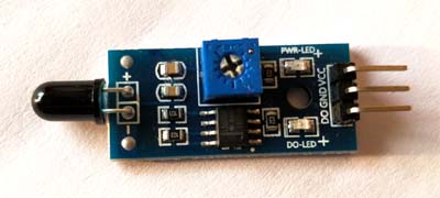
These sensors feature an IR receiver (photodiode) that detects fire. When fire burns, it emits a small amount of infrared light, which is picked up by the IR receiver. An Op-Amp processes the signal and detects voltage changes across the IR receiver. If a fire is detected, the output pin (DO) goes LOW (0V), and if no fire is present, the output pin remains HIGH (5V).
To determine the fire's location, three sensors are placed in different directions on the robot. The below image shows our basic design of a fire fighting robot.
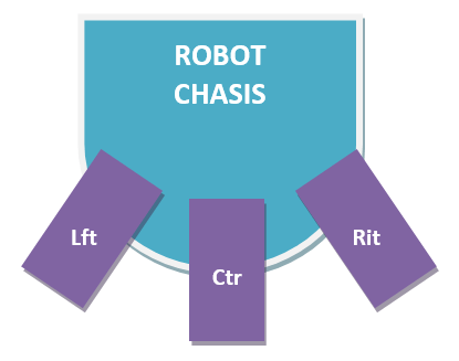
Once the fire's direction is identified, the robot moves toward it using motors controlled via an L293D motor driver module. To extinguish the fire, a small water container is mounted on the robot. A 5V water pump is placed inside the container, and the entire setup is positioned on a servo motor, allowing controlled water spraying in the required direction.
Block Diagram
The block diagram shown below illustrates the working of a fire-fighting robot using an Arduino UNO as the central controller.
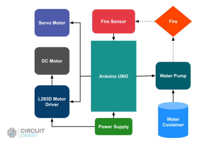
The fire sensor detects flames and sends signals to the Arduino, which processes the input and triggers necessary actions. Once fire is detected, the Arduino activates the water pump, drawing water from the container and spraying it onto the fire to extinguish it.
Simultaneously, the robot moves towards the fire using DC motors controlled by the L293D motor driver. A servo motor helps adjust the nozzle position for accurate water spraying. The entire system operates with a dedicated power supply, ensuring uninterrupted functionality.
Fire Fighting Robot Circuit Diagram
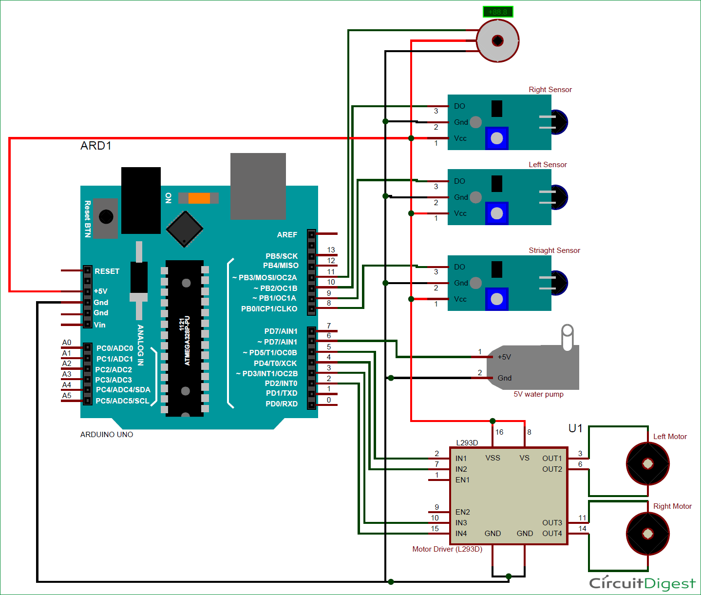
The complete circuit diagram for this Fire Fighting Robot is given below
You can either connect all the shown connections for uploading the program to check the working or you can assemble the bot completely and then proceed with the connections. Both ways the connections are very simple and you should be able to get it right.
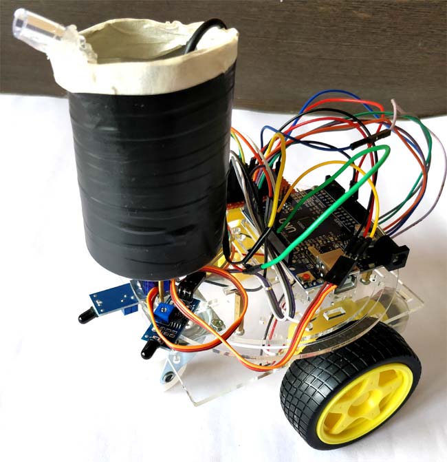
Based on the robotic chassis that you are using you might not be able to use the same type of container that I am using. In that case use your own creativity to set up the pumping system. However the code will remain same. I used a small aluminium can (cool drinks can) to set the pump inside it and poured water inside it. I then assembled the whole can on top of a servo motor to control the direction of water. My robot looks something like this after assembly.
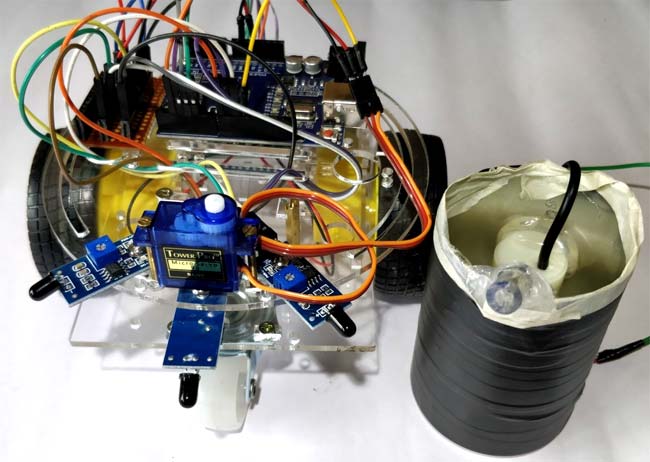
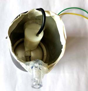
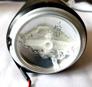
As you can see, I have fixed the servo fin to the bottom of the container using got glue and have fixed the servo motor with chassis using nuts and bolts. We can simply place the container on top of the motor and trigger the pump inside it to pump water outside through the tube. The whole container can then be rotated using the servo to control the direction of the water.
Arduino Code Explanation
Once you are ready with your hardware, you can upload the Arduino code for some action. The complete program is given at the end of this page. However, I have further explained few important bits and pieces here.
As we know the fire sensor will output a HIGH when there is fire and will output a LOW when there is fire. So we have to keep checking these sensor if any fire has occurred. If no fire is there we ask the motors to remain stop by making all the pins high as shown below
    if (digitalRead(Left_S) ==1 && digitalRead(Right_S)==1 && digitalRead(Forward_S) ==1) //If Fire not detected all sensors are zero
    {
    //Do not move the robot
    digitalWrite(LM1, HIGH);
    digitalWrite(LM2, HIGH);
    digitalWrite(RM1, HIGH);
    digitalWrite(RM2, HIGH);
    }
Similarly, if there is any fire we can ask the robot to move in that direction by rotating the respective motor. Once it reaches the fire the left and right sensor will not detect the fire as it would be standing straight ahead of the fire. Now we use the variable named “fire” that would execute the function to put off the fire.
    else if (digitalRead(Forward_S) ==0) //If Fire is straight ahead
    {
    //Move the robot forward
    digitalWrite(LM1, HIGH);
    digitalWrite(LM2, LOW);
    digitalWrite(RM1, HIGH);
    digitalWrite(RM2, LOW);
    fire = true;
    }
Once the variable fire becomes true, the fire fighting robot arduino code will execute the put_off_fire function until the fire is put off. This is done using the code below.
     while (fire == true)
     {
      put_off_fire();
     }
Inside the put_off_fire() we just have to stop the robot by making all the pins high. Then turn on the pump to push water outside the container, while this is done we can also use the servo motor to rotate the container so that the water is split all over uniformly. This is done using the code below
void put_off_fire()
{
     delay (500);
    digitalWrite(LM1, HIGH);
    digitalWrite(LM2, HIGH);
    digitalWrite(RM1, HIGH);
    digitalWrite(RM2, HIGH);
   digitalWrite(pump, HIGH); delay(500);
    for (pos = 50; pos <= 130; pos += 1) {
    myservo.write(pos);
    delay(10);
  }
 for (pos = 130; pos >= 50; pos -= 1) {
    myservo.write(pos);
    delay(10);
  }
  digitalWrite(pump,LOW);
  myservo.write(90);
    fire=false;
}
Working Demonstration of Fire Fighting Robot:
It is recommended to check the output of the robot in steps rather than running it all together for the first time. You can build the robot upto the servo motor and check if it is able to follow the fire successfully. Then you can check if the pump and the servo motor are working properly. You can also check out the working video of Fire Fighting Robot to see this robot in action, the video shows the robot automatically moving towards the flame and pumping water to extinguish the fire.
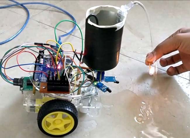
The maximum distance to which the fire can be detected depends on the size of the fire, for a small matchstick, the distance is relatively less. You can also use the potentiometers on top of the modules to control the sensitivity of the robot. I have used a power bank to power the robot you can use a battery or even power it with a 12V battery.
Hope you understood the project and would enjoy building something similar. If you have any problems in getting this build, use the comment section below to post your queries or use the forums for technical help.
Arduino Fire Fighting Robot Code - GitHub
You can find the complete code for the Arduino Fire Fighting Robot Project on the bottom of this page. Additionally, we have also created a GitHub repo for this project for people to easily access the code and other related files.
Common Issues and Solutions
If your line following robot is not working, do not worry it is common for people to face troubles especially if this is your first robot. Here are some common issues with their solutions, these issues were raised by our readers in the comment section below
If the flame sensor is not detecting fire, check its placement and ensure it is positioned correctly to detect flames without obstruction. Adjust the sensor’s sensitivity settings if necessary. Ambient light can sometimes interfere with detection, so test the sensor in different lighting conditions to rule out external interference. Also if you can check out our Arduino Flame Sensor tutorial to understand more about flame sensor and how to use it with arudino.
If the robot is not moving, inspect the motor driver wiring to confirm all connections are secure and properly soldered. The motor driver should be receiving the correct voltage, typically 12V, for optimal performance. Ensure the power source is stable and provides sufficient current to drive the motors.
If the water pump is not spraying, check the relay module and all wiring connections to verify they are intact and correctly configured. The pump should be receiving power when activated. Use a multimeter to check for voltage at the pump terminals and confirm that the relay is switching correctly. If the issue persists, inspect the pump for clogs or mechanical failures.
If you are still facing problems you can post them in the comment section below or write on our forums and we will help you out with troubleshooting.
Conclusion and Future Developments
In this project, we successfully built an Arduino-based Fire Fighting Robot that can detect and extinguish fires autonomously. By integrating flame sensors, a motorized water pump, and a servo-controlled water spray system, the robot efficiently locates and suppresses fires. This simple yet effective design demonstrates the potential of robotics in fire safety applications. With further enhancements, such as advanced sensors and AI-based navigation, this simple arduino based fire fighting robot project can be expanded for real world firefighting scenarios.
Projects Similar to Fire Fighting Robot
If you have successfully completed your firefighting robot project and are looking for more, we got you covered. Here is a list of DIY electronics projects with code and schematics that you build next. All these projects are built by us here in CircuitDigest and uses more or less the same components that is used in this project.
Obstacle Avoidance Robot using Arduino and Ultrasonic Sensor
Obstacle Avoiding Robot is an intelligent device that can automatically sense the obstacle in front of it and avoid them by turning itself in another direction. This design allows the robot to navigate in an unknown environment by avoiding collisions, which is a primary requirement for any autonomous mobile robot.
This robot car can be controlled wirelessly with Bluetooth and an android app, and other than that we have placed RGB Neopixel LEDs on the front, back, and bottom of the robot to make it look cool. We will also build a custom android app with the MIT app inventor so that we can send commands directly via Bluetooth.
Simple Arduino Line Following Robot
Line Follower Robot (LFR) is a simple autonomously guided robot that follows a line drawn on the ground to either detect a dark line on a white surface or a white line on a dark. The LFR is quite an interesting project to work on! In this tutorial, we will learn how to build a black line follower robot using Arduino Uno and some easily accessible components.
Gesture Controlled Robot Using Arduino
Let's build a cool hand gesture-controlled robot that'll amaze your friends and family—it's like magic! This step-by-step guide helps you build a hand gesture-controlled robot using simple components like Arduino, MPU6050 Accelerometer, nRF24L01 Transmitter-Receiver Pair, and L293D motor driver module. We'll split the robot into two parts: the Transmitter and the Receiver.
Light Following Robot using Arduino UNO
Today, we are building a simple Arduino-based project: a light-following robot. This project is perfect for beginners, and we'll use LDR sensor modules to detect light and an MX1508 motor driver module for control.
Complete Project Code
/*------ Arduino Fire Fighting Robot Code----- */
/*------ Code by: www.circuitdigest.com---- */

#include <Servo.h>
Servo myservo;

int pos = 0;
boolean fire = false;

/*-------defining Inputs------*/
#define Left_S 9      // left sensor
#define Right_S 10      // right sensor
#define Forward_S 8 //forward sensor

/*-------defining Outputs------*/
#define LM1 2       // left motor
#define LM2 3       // left motor
#define RM1 4       // right motor
#define RM2 5       // right motor
#define pump 6

void setup()
{
  pinMode(Left_S, INPUT);
  pinMode(Right_S, INPUT);
  pinMode(Forward_S, INPUT);
  pinMode(LM1, OUTPUT);
  pinMode(LM2, OUTPUT);
  pinMode(RM1, OUTPUT);
  pinMode(RM2, OUTPUT);
  pinMode(pump, OUTPUT);

  myservo.attach(11);
  myservo.write(90);
}

void put_off_fire()
{
    delay (500);

    digitalWrite(LM1, HIGH);
    digitalWrite(LM2, HIGH);
    digitalWrite(RM1, HIGH);
    digitalWrite(RM2, HIGH);

   digitalWrite(pump, HIGH); delay(500);

    for (pos = 50; pos <= 130; pos += 1) {
    myservo.write(pos);
    delay(10);
  }
  for (pos = 130; pos >= 50; pos -= 1) {
    myservo.write(pos);
    delay(10);
  }

  digitalWrite(pump,LOW);
  myservo.write(90);

  fire=false;
}

void loop()
{
   myservo.write(90); //Sweep_Servo();

    if (digitalRead(Left_S) ==1 && digitalRead(Right_S)==1 && digitalRead(Forward_S) ==1) //If Fire not detected all sensors are zero
    {
    //Do not move the robot
    digitalWrite(LM1, HIGH);
    digitalWrite(LM2, HIGH);
    digitalWrite(RM1, HIGH);
    digitalWrite(RM2, HIGH);
    }

    else if (digitalRead(Forward_S) ==0) //If Fire is straight ahead
    {
    //Move the robot forward
    digitalWrite(LM1, HIGH);
    digitalWrite(LM2, LOW);
    digitalWrite(RM1, HIGH);
    digitalWrite(RM2, LOW);
    fire = true;
    }

    else if (digitalRead(Left_S) ==0) //If Fire is to the left
    {
    //Move the robot left
    digitalWrite(LM1, HIGH);
    digitalWrite(LM2, LOW);
    digitalWrite(RM1, HIGH);
    digitalWrite(RM2, HIGH);
    }

    else if (digitalRead(Right_S) ==0) //If Fire is to the right
    {
    //Move the robot right
    digitalWrite(LM1, HIGH);
    digitalWrite(LM2, HIGH);
    digitalWrite(RM1, HIGH);
    digitalWrite(RM2, LOW);
    }

delay(300); //Slow down the speed of robot

     while (fire == true)
     {
      put_off_fire();
     }
}
Comments
All the required information
All the required information is already given here by the author. Why don't you start building your final year project?
can i use camera and connect
can i use camera and connect it with my smart phone....and also used US IR MQ sensors...will ARDUINO microcontroller hold all these things?
He has used a 5V pump to pump
He has used a 5V pump to pump the water out of the can. The whole can is mounter on top of a servo motor. The pump is placed inside the can (that is the white plastic thing)
Can you kindly tell me how to
Can you kindly tell me how to select water pump in Proteus and what is the component placed above flame sensors in the circuit diagram (round and have a digital meter on it),
Thanks
The component above the
The component above the sensor is a servo motor. Proteus does not have a pump. The one that is used here was drawn (using the draw options Proteus) to just show you how the connections are done
Assistance
I'm assisting my son who is in middle school on a science project, and we are at a standstill and hoping you can assist us. I've came across your video and it seemed relatively close to what we hope to accomplish. We are trying to make a voice/(phrase) command volcano that erupts so far we found instructions to make the classic science fair volcano but have run into difficulty coding and assembling to make it erupt on command. How would you make the fire fighting bot shoot water on voice/phrase command. Can you please help us?
Hi alanna,
Hi alanna,
I assume you have used a pump inside your volcano which when activated would pump some water(Lava) outside the volcano. Now to turn on this pump using voice command is no easy task and would surely be an overkill for a science fair.
However if you want to do it, you can follow this tutorial below where a Light is turned on using Voice command, you just have to replace the light with your pump
https://circuitdigest.com/microcontroller-projects/iot-based-voice-cont…
A more easy way would be to turn on the pump for the sound of a clap (or any large noise). This would be a lot more easy. The circuit for same is shared below. Instead of controlling led you can control your pump
https://circuitdigest.com/electronic-circuits/simple-led-music-light
Hope this would help you to assist your young champ. If you need more help please use the forums
can you send me the documentation of fire fighting robot systm
can you send me the documentation of fire fighting robot systm
my email is [email protected]
can i use camera and connect
can i use camera and connect it with my smart phone... plusIR US MQ sensors..will microcontroller of arduino hold that much power or shoul i go for rasberry pi
water pump is not working
water pump is not working after the flame is detected help me to solve these problem
I want to make the same
I want to make the same project but make the robot avoid obstacles using ultrasonic sensor ans use only one fire sensor
What is circle above 3 sensor
Hello
What is circle above the three sensor
Will this fire sensor also
Will this fire sensor also detects the smoke. If no , how can we do the same project to fight against smoke also.
No this sensor does not
No this sensor does not detect smoke. To detect smoke you can use the MQ sensor
Fire fighting robot
This project is interesting.i want to know why we use Arduino uno instead of any other kit here and will it work similar if i replace arduino with any other ic cheap set?
Yes, you can use any MCU in
Yes, you can use any MCU in place of arduino. But if you are a very beginner its good to start with Arduino itself
circuit diagram and ultrasonic sensor
can u give me circuit diagram also ?How can we connect ultrasonic sensor with this
Circuit diagram is given
Circuit diagram is given above. Yes you can also connect a US sensor to avoid obstacles if you are intrested
l293d motor driver module
hi,your project is amazing but my L293d motor driver module is having only 7 plugs how is your having 14 plugs?
i have also checked for L293d ic it is having 16 plugs
How to connect the breadboard
How to connect the breadboard can you explain
May i know how many flame
May i know how many flame sensors and servo motor SG90 needed for this project?
can I use a fan instead of a
can I use a fan instead of a water pump and still use the same code and connection?
Water pump is not working when connected to 6 no. Pin
What should I do if water pump is not working when connected to 6 number pin of arduino.but it is working when it is connected between +5V and ground. I guess the pump is not receiving enough voltage when connected to arduino.Is there any solution to solve this problem. Please reply as soon as possible.
Yes,,,I can face problem water pump can't work
Im connected one motor pin connected to Arduino pin 6 and second one is connected to GND,but water pump doesn't work,can u help me this issue
Yes,,,I can face problem water pump can't work
My mail id. [email protected],plse anybody sent codes resolve my issue
bro how to solve the problem
bro how to solve the problem of water pump
about the op amp
in the concept of the project there is an op amp said back there, so does the op amp needed ? if needed what ic number will i use ? because im so confused thank you.
No Op-Amp is used here. Why
No Op-Amp is used here. Why are you confused? Just follow the circuit diagram and build the project
can you provide your
can you provide your materials picture? Because im new in coding and wiring things. So im afraid i buy the wrong items but have similar name
Problem in moving the fire fighting robot
Hi.. I have connected all the components as mentioned above. But I have a problem in moving the chasis and pumping out the water. Can you please help asap??
What problem are you facing?
What problem are you facing? did you get any errors? What help do you need?
It is not working
I connect the enther circuit and upload the program to adruino that not in working
HI, the l293D used is an IC
HI, the l293D used is an IC or motor driver?
I'm using a motor driver module
My dc motor won't move and my water pump isn't working
Did you experience any
Did you experience any problems regarding connecting of the servo motor? Ours keeps on moving even though there is no flame. The flame sensors however, lights up when there is a flame but both the motor and the servo is not working. Hoping for your kind reply asap. Thank you.
Audrino Fire Robot Issue
Hi,
I am having the same issue that Maria reported, robot does not stop at flame and no action from servo motor. Is there a fix?
From Maria...Maria Mercedes
reply
Did you experience any problems regarding connecting of the servo motor? Ours keeps on moving even though there is no flame. The flame sensors however, lights up when there is a flame but both the motor and the servo is not working. Hoping for your kind reply asap. Thank you.
The reason for you robot to
The reason for you robot to move when there is no fire is because the flame sensors will react to IR rays. IF there is excess sunlight inside the room, the sensor would read the IR rays from sun and assume it to be fire.
IF your motors and servo are not working, the problem should be on the hardware. Try running a small servo sweep program (example program in arduino) and check if the motors are functional
in the connection circuit
in the connection circuit you have provided, you have not shown the connection between arduino and bred board, please help
The perfboard that you find
The perfboard that you find in the project is just optional. Just follow the circuit diagram and make the conections
Fire fighter robot
It is not working .....I connect properly all the components also upload code in arduino...Bt it is not working....Plzz held me for getting output
What problem are you getting?
What problem are you getting? explain the problem and only then I will be able to help you
Sir... I connect all
Sir... I connect all components shown in diagram .....I give 9v power supply to ardino .... Upload the code you given...Bt the problem is that the ardino not get power to motor drive and fire sensor......Its not work .....I give 9v power supply to ardino bt the fire sensor also off
not enough power
the power i give in is either enough to run the servo motor and sensors or the wheels..not both at the same time. what can be done to increase the input power. if one works the other stops
How are you powering your
How are you powering your Arduino?
Are you using the same servo, pump and motor?
Try powering the Arduino through phone charger (1A).
If you are tyring with 9V battery then it wont work
Alohol sensor
automatic engine locking system when using alcohol sensor,plse anybody have,can u sent me,my mail id : [email protected]
My the gear motor and water
My the gear motor and water pump is 12v .is it possible to connect it into the arduino board directly?
Can u please tell me where is
Can u please tell me where is the connection of servo motor
project
hii ......i am building a similar project...wen im connecting the 9G servo motor and the pump together with the arduino, the servo does'nt sweep properly, instead it gets stuck to one position. the pump which i used is a 6V one. Any solutions for that ?????
What is the procedure to build the fire fighting robot?
I want video with explanation, step-by-step procedure of the project and also study materials for the project of fire fighting robot using arduino uno. Please can you make this as soon as possible
how to power the pump
In the circuit the pump is nt given any power so how it will work how to give that 5v to the pump?
L293D Motor Driver
Hi there,
Can i use the motorshield L293d? what supposed to be the pin out? will the sketch program for Arduino change? Need reply ASAP . Thank you for a great project!
how much power will this
how much power will this project needs?
How can we increase the range
How can we increase the range of sensors??
You can vary the
You can vary the potentiometer on the sensor module to increase the range. Also if the room does not have heavy sunlight it will work much better
Code not running
Me and my friend are working on this fire fighting robot and are unable to run the code, as the bot is not working.
HI,
HI,
i'v been working on the same since days. The sensors and the servomotor (below the can) seems working good. The LM and RM are not responding any how, is there any other way i can run my L&R motor except L293D? The 5v water pump is not receiving enough voltage form the arduino uno board. Please help.
Thank you.
Arduino Based Fire Fighting Robot
Hi i need full programming and technical report and wiring and exact connections of arduino and all please send it to my mail at [email protected]
regards,
Haris Manzoor
hi sire,i am working on one
hi sire,i am working on one project to bulid montring system for elctricity transformer ,so i want to check and see your works,hopefull will help me on my work,may i see your work please
also if you send it to me ,i will be happy
Power supply and motor driver
How much power supply u used ,u mentioned only 12v u didn't shown it in video.and I use 4wd chassis I have to use 4wd motor driver ,how to connect it . otherwise can it possible to connect another back wheels common with front is it works?
How to define the distance
How to define the distance between fire sensor and flame....what should I do for When fire detect an bot forward towords fire and stop in specific distance.....
Hi! What could be the problem
Hi! What could be the problem if the wheels don't work when there is a fire? Also, the servo motor works right away when the arduino is connected to the laptop? Please reply ASAP, thank you very much!!
Fire fighter Robot
In the components there was a breadboard. The robot was also maken by breadboard. But in the circuit diagram there is no breadboard. Is there any need of using breadboard?
left and right motors are not
left and right motors are not working ??
Water pump
Water pump of 5v as only two wire red and black those are connected to 5v and ground....thn water will be pumped continuously...so how will the water pump knows Wen it has to pump
Hello sir..I have used 2 DC
Hello sir..I have used 2 DC motors for chessy board for the motion of the fire brigade.Is there any variations we have to do? or the program you have given??
Are the motors connected with
Are the motors connected with L293D motor driver? If yes then there are not corrections required
project not working
please sir help me . my project is not working properly . when i connect audiuno to laptop, it will automatically rotating wheels and micro server. please send me its proper circuit diagram and program. i am very thankfull if you helping me.
fire fighting robot
i will replace the tip by much stronger nozzle , so what will i modify in the code to increase the range of the sensor ?
i want larger distance when the robot sense the fire move a bit and start the pump and the servo motor
Yes mohamed you can try that.
Yes mohamed you can try that. Also make sure the room does not have direct sunlight. Because that will also affect the range
Pump is not working
When I connect the pump, pump is not working but all robot does. Pump and servo motor are not working at same time. Help me.
Fire Fighting Robot
My servo motor is not working for left and right sensor . For middle sensor its working fine . Can anyone give me any aolution ?
L293D MODULE PURCHASE LINK
Could you please give me exactly what type of .module used either post photos of that module or purchase link.
i need full arduino code
i need full arduino code please
Thank you :)
Help to connect fire sensors into arduino
Hi There, It is my first time getting hands on this type of project it is really awesome and interesting.
I am working in a school project and since I do not have any experience at all I would like your expertise help to guide me through. I do have the robot car already just need help to connect the fire sensor and make them work.
Robot not working Properly
I have uploaded the code and connection all the connections properly but the robot in not working properly, I have made following connections:
1. a 12v battery to supply enough current to the motors (i am using 4 tires chasing) through L239D.
2. Through this battery I have supplied voltages to arduino at "Vin" port.
3. L239D is also directly connected to 12V Battery (at 12v Dc terminal of L239D and ground obviously).
4. I have taken 5v from arduino 5v port and have supplied it to flame sensor (using a 5 channel flame sensor module) , servo motor and the water pump according to the diagram with the arduino.
I am facing the following issues:-
1. Robot is continuously moving forward(3 secs move, 3 secs stop then repeat)
2. Servo Motor is continuously rotating according to the code irrespective of flame detection.
3. Flame sensor is sensing the flame properly but pump is not spraying water (never).
Kindly guide me how to resolve the issues.
Thank you
Hi Mudasir,
Hi Mudasir,
Your connections are all correct. It should have worked properly. Was there direct sunlight inside the room in which you were testing?
I suggest you to debug by yourself, it can be easily done by adding some Seril.println() lines inside the program to figure out why the bot is responding badly. Hope you get it working.
L293D motor Driver module
Hi B.Aswinth Raj,
I would like to ask for your help in where can I buy the correct L293D motor Driver module for this project. i have tried but there are a lot of options and no one looks like the one shown in the diagram.
Sorry for being so naive but it is the first project and I am helping my daughter to build this project that is due in a week have not tested yet either due to I am missing L293D motor Driver module to connect the final wires. do you happen to have a link where I can see a all the project step by step? the diagram its self explanatory but I am running out of time :(



i want video with explanation, step-by-step implementation of hardware, block diagram of the project and also study materials for the project of fire fighting robot using arduino uno. please help me............. for the final year project submission...