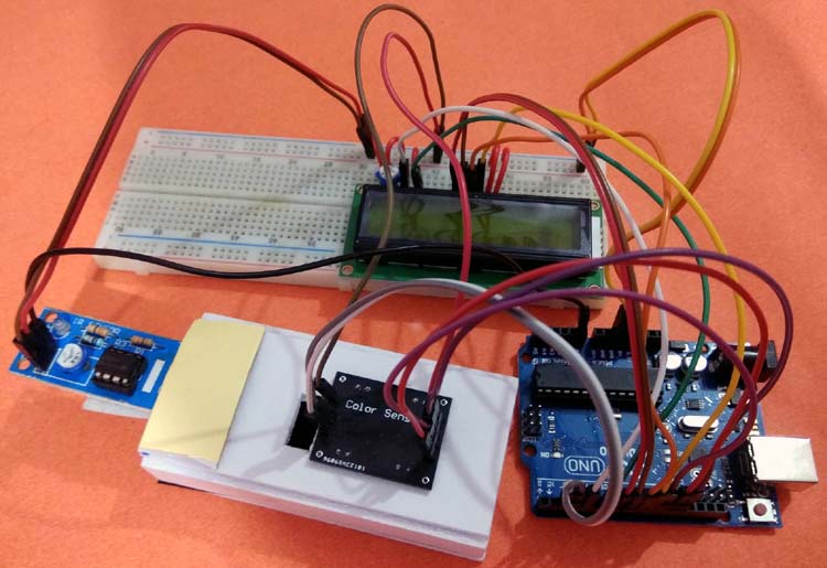
In this project we are going to work on an innovative arduino project idea, where we can count the paper currency notes and calculate their amount, by sensing the paper currency using Color Sensor and Arduino. TCS230 color sensor will be used for detecting the currency notes and, Arduino UNO for processing the data and showing the remaining balance on 16x2 LCD.
Required Components:
- Arduino UNO
- TCS230 Colour sensor
- IR sensor
- Breadboard
- 16*2 Alphanumeric LCD
- Connecting Wires
TCS3200 Color Sensor Working
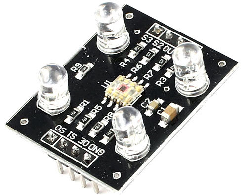
The TCS3200 color sensor is used to sense a wide range of colors. We previously interfaced TCS3200 color sensor with Arduino and Raspberry pi, and also built some useful projects like Color sorting machine.
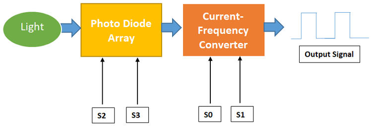
TCS230 sensor has inbuilt infrared LEDs that are used to light up the object whose colour is to be detected. This ensures that there will no impacts of external surrounding light on the object. This sensor reads a photodiode of 8*8 array, which comprises of 16 photodiodes with red filters, 16 with blue filters, 16 with green filters and 16 photodiodes without any filter. Each of the sensor arrays in these three arrays is selected separately depending on the requirement. Hence it is known as a programmable sensor. The module can be featured to sense the particular color and to leave the others. It contains filters for that selection purpose. There is a fourth mode called ‘no filter mode’ in which the sensor detects white light.
The output signal of the TCS230 colour sensor is a square wave with a 50% duty cycle and its frequency is proportional to the light intensity of the selected filter.
Pinout of TCS3200 Color Sensor:
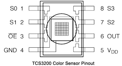
VDD- Voltage supply pin of Sensor. It is supplied with 5V DC.
GND- Ground reference pin of a colour sensor
S0, S1- Output frequency scaling selection inputs
S2, S3- Photo-diode type selection inputs
OUT- Output pin of a colour sensor
OE- Enable pin for output frequency
We have also used an IR sensor in this project, whose working can be understood by the following link.
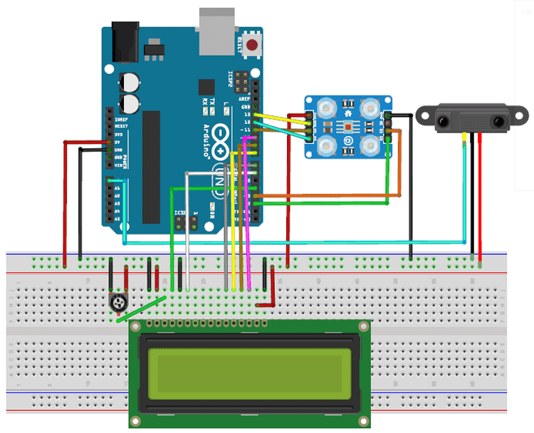
Circuit Diagram
Below is the circuit diagram for the Arduino Money Counter:
Here, I have made a small structure like a POS currency swiping machine using cardboards. In this structure, a colour sensor and an IR sensor are fixed with the cardboard like shown in the image below.
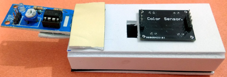
Here the IR sensor is used to sense the presence of currency inside the slot and if there is a note, then the colour sensor will detect the color of the Note and send the color value to Arduino. And Arduino further calculates the currency value based on the color of the note.
Code Explanation
Complete code along with a demo video is given at the end of the article. Here the stepwise explanation of the complete code is given below.
First, include all the libraries in the program. Here we only need the LCD library to be included in the program. Then declare all the variables used in the code.
#include <LiquidCrystal.h>
int OutPut = 13;
unsigned int frequency = 0;
LiquidCrystal lcd(4, 6, 7, 8, 9, 10);
int blue1;
int red1;
int green1;
int a = 0, b = 0;
int total = 1000;
Inside setup (), print the welcome message on LCD and define all the data directions of digital pins used in this project. Next, set the output frequency scaling of the colour sensor, in my case, it is set to 20% which can be set by giving HIGH pulse to S0 and LOW pulse to S1.
void setup()
{
  Serial.begin(9600);
  lcd.begin(16, 2);
  lcd.setCursor(0, 0);
  lcd.print("  Smart Wallet  ");
  lcd.setCursor(0, 1);
  lcd.print(" Circuit Digest  ");
  delay(2000);
  lcd.clear();
  pinMode(2, OUTPUT);//S0
  pinMode(3, OUTPUT);//S1
  pinMode(11, OUTPUT);//S2
  pinMode(12, OUTPUT);//S3
  pinMode(13, INPUT);//OUT
  digitalWrite(2, HIGH);
  digitalWrite(3, LOW);
}
Inside infinite loop (), read all the data outputs from the sensors. The output from the IR sensor can be found by reading the A0 pin and output colour frequencies can be found by calling the individual functions written as red (), blue () and green (). Then print all of them on the Serial monitor. This is needed when we need to add a new currency to our project.
int sensor = digitalRead(A0);
  int red1 = red();
  int blue1 = blue();
  int green1 = green();
  Serial.println(red1);
  Serial.println(blue1);
  Serial.println(green1);
  Serial.println("-----------------------------");
Next, write all the conditions to check the output frequency of the colour sensor with the reference frequency which we have set before. If it matches, then deducts the specified amount from the wallet balance.
  if (red1>=20 && red1<=25 && blue1 >=30 && blue1 <=35 && green1 >=30 && green1 <=35 && a == 0 && sensor == HIGH)
  {
    a = 1;
  }
  else if (sensor == LOW && a == 1)
  {
    a = 0;
    if(total>=10)
    {
    lcd.setCursor(0, 1);
    lcd.print("10 Rupees!!!");
    total=total-10;
    delay(1500);
    lcd.clear();
    }
  }
Here we have only set the conditions for 10 Rupees and 50 Rupees Note color, you can set more conditions to detect more no. of currency notes.

Note: The frequency output may be different in your case depending on the external lighting and sensor setup. So it is recommended to check the output frequency of your currency and set the reference value accordingly.
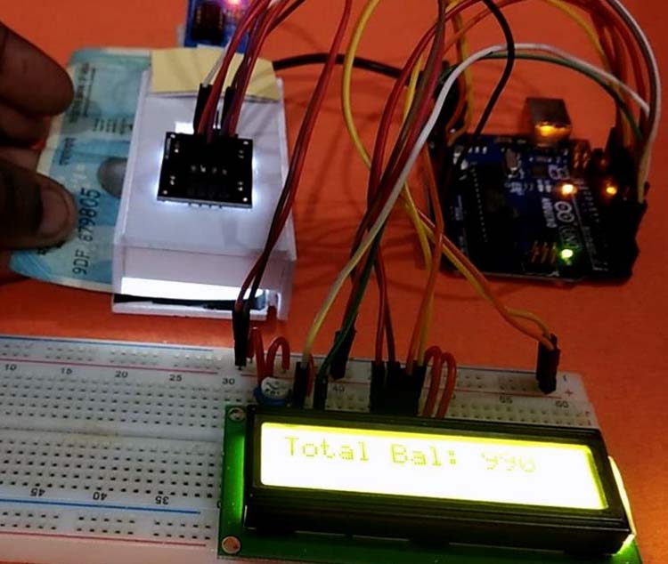
The below code will show the available balance in the wallet on the 16x2 LCD.
  lcd.setCursor(0, 0);
  lcd.print("Total Bal:");
  lcd.setCursor(11, 0);
  lcd.print(total);
  delay(1000);
The following function will get the output colour frequency of red content in the currency. Similarly, we can write other functions to get value for blue and green colour contents.
int red()

{

  digitalWrite(11, LOW);
  digitalWrite(12, LOW);
  frequency = pulseIn(OutPut, LOW);
  return frequency;
}
So this is how an Arduino based Money counter can be built easily using few components. We can further modify it by integrating some image processing and camera to detect the currency using the image, that way it will be more accurate and will be able to detect any currency.
Complete Project Code
int OutPut = 13;

unsigned int frequency = 0;

#include <LiquidCrystal.h>

LiquidCrystal lcd(4, 6, 7, 8, 9, 10);

int blue1;

int red1;

int green1;
int a = 0, b = 0;

int total = 1000;

void setup()

{

  Serial.begin(9600);

  lcd.begin(16, 2);

  lcd.setCursor(0, 0);

  lcd.print("  Smart Wallet  ");

  lcd.setCursor(0, 1);

  lcd.print(" Circuit Digest  ");

  delay(2000);
  lcd.clear();
  pinMode(2, OUTPUT);//S0

  pinMode(3, OUTPUT);//S1

  pinMode(11, OUTPUT);//S2

  pinMode(12, OUTPUT);//S3

  pinMode(13, INPUT);//OUT
  digitalWrite(2, HIGH);

  digitalWrite(3, LOW);

}
void loop()

{

  int sensor = digitalRead(A0);

  int red1 = red();

  int blue1 = blue();

  int green1 = green();
  Serial.println(red1);

  Serial.println(blue1);

  Serial.println(green1);

  Serial.println("-----------------------------");


  if (red1>=20 && red1<=25 && blue1 >=30 && blue1 <=35 && green1 >=30 && green1 <=35 && a == 0 && sensor == HIGH)

  {

    a = 1;

  }

  else if (sensor == LOW && a == 1)

  {

    a = 0;

    if(total>=10)

    {

    lcd.setCursor(0, 1);

    lcd.print("10 Rupees!!!");

    total=total-10;

    delay(1500);

    lcd.clear();

    }

  }

  if (red1 >= 25 && red1 <= 30 && blue1 >= 30 && blue1 <= 33 && green1 >= 25 && green1 <=30 && b == 0 && sensor == HIGH)

  {

    b = 1;

  }

  else if (sensor == LOW && b == 1)

  {

    b = 0;

    if(total>=50)

    {

    lcd.setCursor(0, 1);

    lcd.print("50 Rupees!!!");

    total=total-50;

    delay(1500);

    lcd.clear();

    }

  }

  lcd.setCursor(0, 0);

  lcd.print("Total Bal:");

  lcd.setCursor(11, 0);

  lcd.print(total);

  delay(1000);

}
int red()

{

  digitalWrite(11, LOW);

  digitalWrite(12, LOW);

  frequency = pulseIn(OutPut, LOW);

  return frequency;

}

int blue()

{

  digitalWrite(11, HIGH);

  digitalWrite(12, HIGH);

  frequency = pulseIn(OutPut, LOW);

  return frequency;

}

int green()

{

  digitalWrite(11, LOW);

  digitalWrite(12, HIGH);

  frequency = pulseIn(OutPut, LOW);

  return frequency;

}



THIS IS A GREAT IDEA. I REALLY LIKED THIS AND I'M DOING THE SAME.
THE PROJECT IS SIMPLE TO BUILD ON AND EASY TO UNDERSTAND. THANKS FOR THE VIDEO TOO.