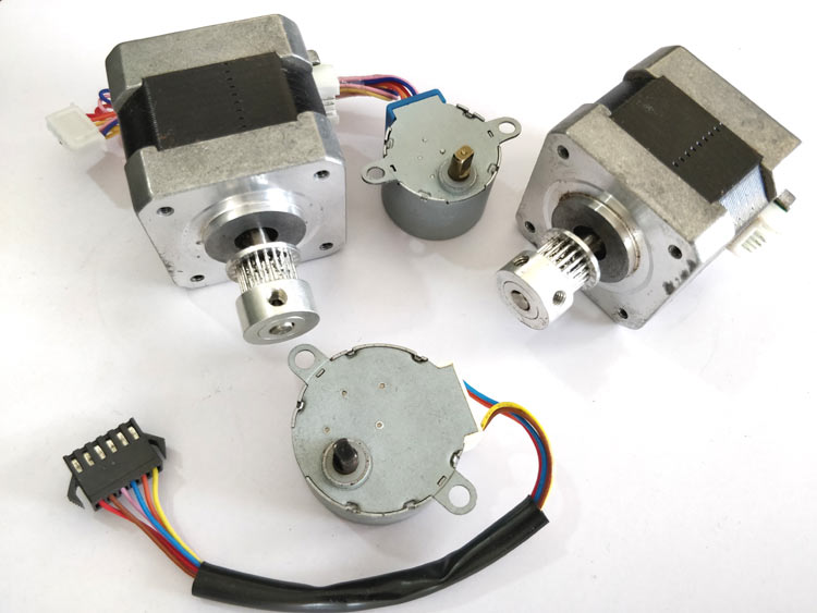
From a simple DVD player or printer in your home to a highly sophisticated CNC machine or Robotic Arm, Stepper motors are to be found almost everywhere. Its ability to make electronically controlled precise movements have made these motors find application in many felids like surveillance cameras, Hard disk, CNC machines, 3D Printers, Robotics, Assembly robots, Laser cutters and much more. In this article let us learn what makes these motors special and the theory behind it. We will learn how to use one for you application.
Introduction to Stepper Motors
Like all motors the stepper motors also have a stator and a rotor, but unlike a normal DC motor the stator consists of individual sets of coils. The number of coils will differ based on type of stepper motor, but for now just understand that in a stepper motor the rotor consists of metal poles and each pole will be attracted by a set of coil in the stator. The below diagram shows a stepper motor with 8 stator poles and 6 rotor poles.
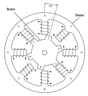
If you take a look at the coils on the stator, they are arranged in terms of coil pairs, like A and A’ forms a pair B and B’ forms a pair and so on. So each of this coil pair’s form an electromagnet and they can be energised individually using a driver circuitry. When a coil gets energised it acts as a magnet and the rotor pole gets aligned to it, when the rotor rotates to adjust itself to align with the stator it is called as one step. Similarly by energising the coils in a sequence we can rotate the motor in small steps to make a complete rotation.
Types of stepper motors
There are mainly three types of stepper motors based on construction, which are:
- Variable reluctance stepper motor: They have iron core rotor which is attracted towards the stator poles and provide movement by minimum reluctance between stator and rotor.
- Permanent magnet stepper motor: They have permanent magnet rotor and they are repelled or attracted towards the stator according to pulses applied.
- Hybrid synchronous stepper motor: They are combination of Variable reluctance and permanent magnet stepper motor.
Apart from this we can also classify the stepper motors as Unipolar and Bipolar based on the type of stator winding.
- Bipolar Stepper Motor: The stator coils on this type of motor will not have a common wire. The driving of this type of stepper motor is different and complex and also the driving circuit cannot be easily designed without a microcontroller.
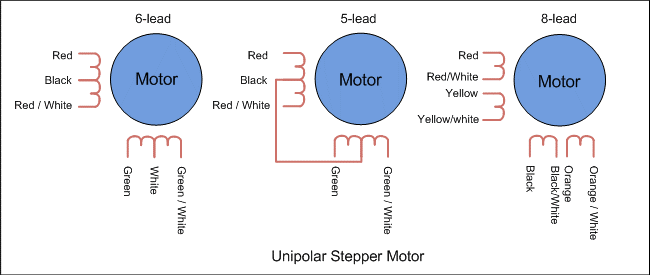
- Unipolar Stepper Motor: In this type of stepper motor we can take the center tapping of both the phase windings for a common ground or for a common power as shown below. This makes it easy to drive the motors, there are many types in Unipolar stepper motor as well
Modes of operation in Stepper Motor
Since the stator of the stepper mode is built of different pairs of coils, each coil pair can be excited in many different methods, this enabling the modes to be driven in many different modes. The following are the broad classifications
Full Step Mode
In full step excitation mode we can achieve a full 360° rotation with minimum number of turns (steps). But this leads to less inertia and also the rotation will not be smooth. There are further two classifications in Full Step Excitation, they are one Phase-on wave stepping and two phase-on mode.
1. One phase-on stepping or Wave Stepping: In this mode only one terminal (phase) of the motor will be energised at any given time. This has less number of steps and hence can achieve a full 360° rotation. Since the number of steps is less the current consumed by this method is also very low. The following table shows the wave stepping sequence for a 4 phase stepper motor
| Step | Phase 1 | Phase 2 | Phase 3 | Phase 4 |
| 1 | 1 | 0 | 0 | 0 |
| 2 | 0 | 1 | 0 | 0 |
| 3 | 0 | 0 | 1 | 0 |
| 4 | 0 | 0 | 0 | 1 |
2. Two Phase-on stepping: As the name states in this method two phases will be one. It has the same number of steps as Wave stepping, but since two coils are energised at a time it can provide better torque and speed compared to the previous method. Although one down side is that this method also consumes more power.
| Step | Phase 1 | Phase 2 | Phase 3 | Phase 4 |
|
1 |
1 |
1 |
0 |
0 |
|
2 |
0 | 1 | 1 | 0 |
| 3 | 0 | 0 | 1 | 1 |
| 4 | 1 | 0 | 0 | 1 |
Half Step Mode
The Half Step mode is the combination of one phase-on and two-phase on modes. This combination will help us to get over the above mentioned disadvantage of the both the modes.
As you might have guessed it since we are combining both the methods we will have to perform 8-steps in this method to get a complete rotation. The switching sequence for a 4-phase stepper motor shown below
|
Step |
Phase 1 |
Phase 2 |
Phase 3 |
Phase 4 |
|
1 |
1 |
0 |
0 |
0 |
|
2 |
1 |
1 |
0 |
0 |
|
3 |
0 |
1 |
0 |
0 |
|
4 |
0 |
1 |
1 |
0 |
|
5 |
0 |
0 |
1 |
1 |
|
6 |
0 |
0 |
0 |
1 |
|
7 |
1 |
0 |
0 |
1 |
|
8 |
1 |
0 |
0 |
0 |
Micro Step Mode
Micro stepping mode is the complex of all, but it offers very good precision along with good torque and smooth operation. In this method the coil will be excited with two sine waves which are 90° apart. This way we can control both the direction and amplitude of the current flowing through the coil which helps us to increase the number of steps the motor has to make for one complete rotation. Micro stepping can take as high as 256 steps to make one complete rotation, this makes the motor to rotate faster and smoother.
How to use a Stepper Motor
Enough of boring theory, let’s assume someone gives you a stepper motor say the famous 28-BYJ48 and you are really curious to make it work. By this time you would have understood that it is not possible to make these motors rotate by just powering them through a supply, so how would you do it?
Let us take a look at this 28-BYJ48 Stepper motor.
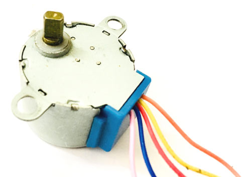
Okay, so unlike a normal DC motor this one has five wires of all fancy colors coming out of it and why is it so? To understand this we should first know how a stepper which we already discussed. First of all steppers motors do not rotate, they step and so they also known as step motors. Meaning, they will move only one step at a time. These motors have a sequence of coils present in them and these coils have to be energized in a particular fashion to make the motor rotate. When each coil is being energized the motor takes a step and a sequence of energization will make the motor take continuous steps, thus making it to rotate. Let us take a look at the coils present inside the motor to know exactly know from where these wires come from.
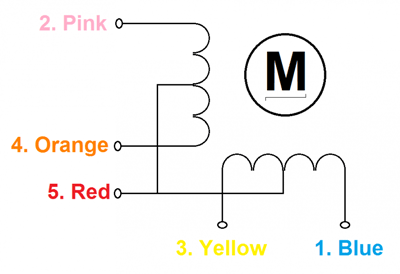
As you can see the motor has unipolar 5-lead coil arrangement. There are four coils which have to be energized in a particular sequence. The Red wires will be supplied with +5V and the remaining four wires will be pulled to ground for triggering the respective coil. We use any microcontroller to energize these coils in a particular sequence and make the motor perform the required number of steps. Again there are many sequence you can use, normally a 4-step is used and for more precise control an 8-step control can also be used. The sequence table for 4-step control is shown below.
|
Step |
Coil Energised |
|
Step 1 |
A and B |
|
Step 2 |
B and C |
|
Step 3 |
C and D |
|
Step 4 |
D and A |
So now, why is this motor called the 28-BYJ48? Seriously!!! I don’t know. There is no technical reason for this motor for being named so; maybe we should not dive much deeper into it. Let us look at some of the important technical data obtained from the datasheet of this motor in the picture below.
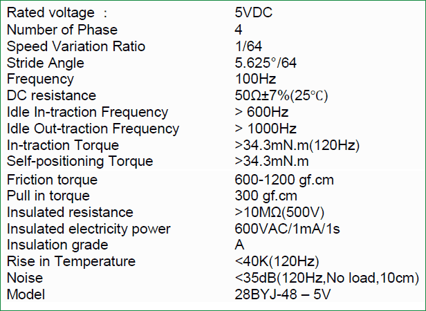
That is a head full of information, but we need to look at few important ones to know what type of stepper we are using so that we can program it efficiently. First we know that it is a 5V Stepper motor since we energize the Red wire with 5V. Then, we also know that it is a four phase stepper motor since it had four coils in it. Now, the gear ratio is given to be 1:64. This means the shaft that you see outside will make one complete rotation only if the motor inside rotates for 64 times. This is because of the gears that are connected between the motor and output shaft, these gears help in increasing the torque.
Another important data to notice is the Stride Angle: 5.625°/64. This means that the motor when operates in 8-step sequence will move 5.625 degree for each step and it will take 64 steps (5.625*64=360) to complete one full rotation.
Calculating the Steps per Revolution for Stepper Motor
It is important to know how to calculate the steps per Revolution for your stepper motor because only then you can program/drive it effectively.
Lets assume we will be operating the motor in 4-step sequence so the stride angle will be 11.25° since it is 5.625°(given in datasheet) for 8 step sequence, it will be 11.25° (5.625*2=11.25).
Steps per revolution = 360/step angle
Here, 360/11.25 = 32 steps per revolution.
Why do we need Driver modules for Stepper Motors?
Most stepper motors will operate only with the help of a driver module. This is because the controller module (Microcontroller/Digital circuit) will not be able to provide enough current from its I/O pins for the motor to operate. So we will use an external module like ULN2003 module as stepper motor driver. There are a many types of driver module and the rating of one will change based on the type of motor used. The primary principle for all driver modules will be to source/sink enough current for the motor to operate. Apart from that there are also driver modules which have the logic pre-programmed into it, but we will not discuss about it here.
If you are curious to know how to rotate a stepper motor using some microcontroller and driver IC, then we have covered many articles on its operation with different microcontrollers:
- Interfacing Stepper Motor with Arduino Uno
- Interfacing Stepper Motor with STM32F103C8
- Interfacing Stepper Motor with PIC Microcontroller
- Interfacing Stepper Motor with MSP430G2
- Stepper Motor Interfacing with 8051 Microcontroller
- Stepper Motor Control with Raspberry Pi
Now I believe you have enough information to control any stepper motor that you require for your project. Let’s take a look at the advantage and disadvantage of Stepper motors.
Advantages of Stepper motors
One major advantage of stepper motor is that it has excellent position control and hence can be used for precise control application. Also it has very good holding torque which makes it an ideal choice for robotic applications. Stepper motors are also considered to have high life time than normal DC or servo motor.
Disadvantages of Stepper Motors
Like all motors Stepper Motors also come with its own disadvantages, since it rotates by taking small steps it cannot achieve high speeds. Also it consumes power for holding torque even when it is ideal thus increasing the power consumption.



Hi, I think this article is great, however I think there might be a mistake in the Half Step Mode table, in steps 5-8 where step 5 should just be phase 3, and what currently are steps 5-7 should become steps 6-8. Either way, the rest of the article is very helpful, thanks!