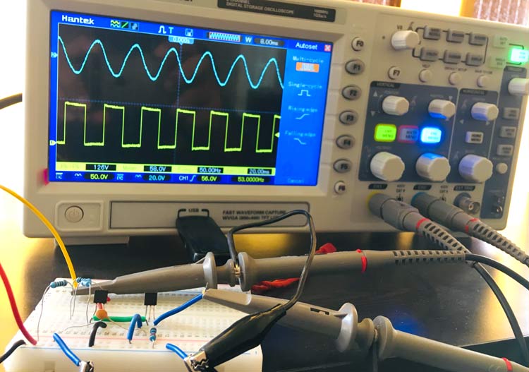
Amplifiers are integral part of Electronics which are used to amplify low amplitude signals. Amplifier plays a very important role to boost the signal, specially in Audio and power electronics. We previously built many types of amplifiers including audio amplifiers, power amplifiers, operational amplifiers etc. Apart from them you can learn many other commonly used amplifiers by following the below links:
Every amplifier has different class and application. Generally transistors and op-amps are used to build amplifier. Here, in this project we learn about Bootstrap Amplifier.
What is Bootstrapping?
Typically Bootstrapping is technique where some part of output is used at the startup. In Bootstrap amplifier, bootstrapping is used to increase the input impedance. Due to which the loading effect on the input source also decreases. The design looks similar to the Darlington pair, having a bootstrap capacitor. Bootstrap capacitor is used to provide AC signal’s positive feedback to the base of the transistor. This positive feedback help in improving the effective value of the base resistance. This increment in the base resistance also determined by the voltage gain of the amplifier circuit.
Why do we need High Input Impedance for Amplifier Transistor?
High input impedance improves the amplification of the input signal and thus required in various amplifier applications. If we have low input impedance we will get low amplification. Generally, BJT (Bipolar Junction Transistor) have low input impedance (typically 1 ohm to 50 kilo ohm). So for this, bootstrapping technique is used to increase the input impedance.
The voltage across the input impedance is calculated by using the below formula:
V = {(Vin.Zin) / (Vin + Z.Vin)}
Hence, according to the formula, the input impedance is proportional to the voltage across it. If the input impedance is increased the voltage across it will also increase and vice versa.
Components Required
- NPN Transistor – BC547
- Resistor – 1k, 10k
- Capacitor – 33pf
- AC or Pulse Input Signal
- DC supply – 9V or 12V
- Breadboard
- Connecting wires
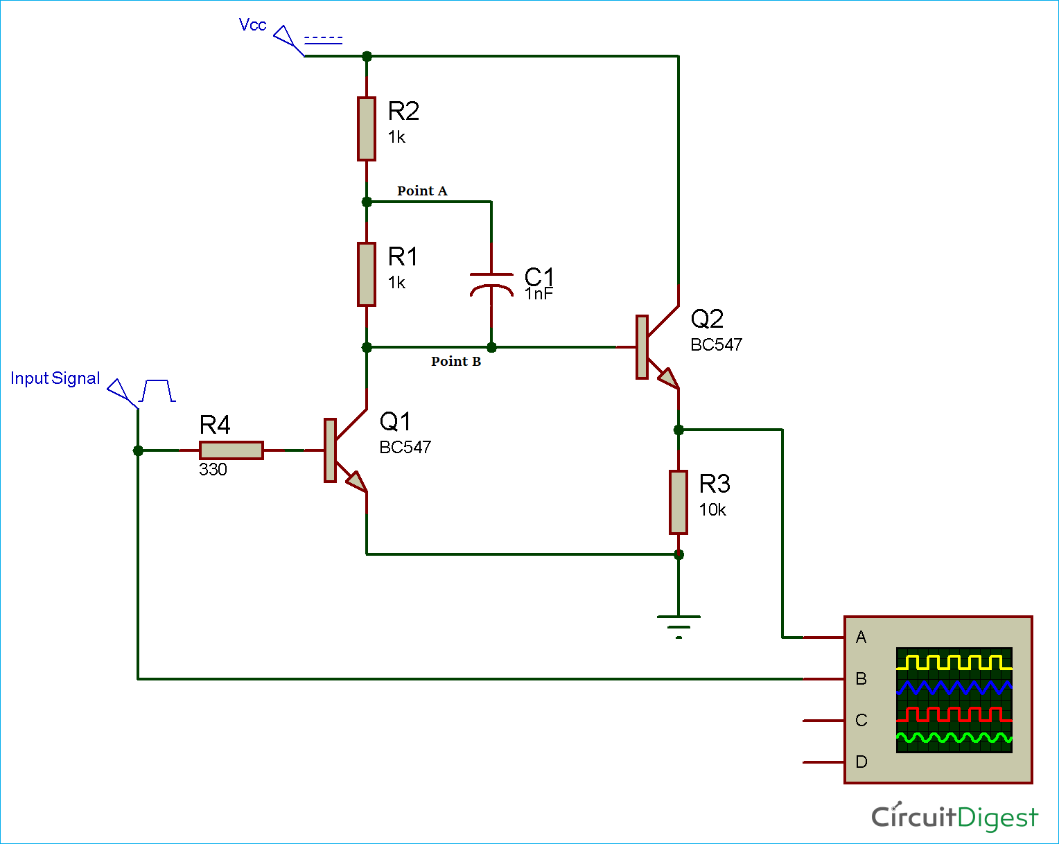
Circuit Diagram
For the input pulse signal, we have used an AC signal (using transformer), you can also use PWM input. And, for the Vcc input, we are using the RPS (Regulated positive supply) in the circuit. Maintain the distance between the AC and DC wire for safety reasons.
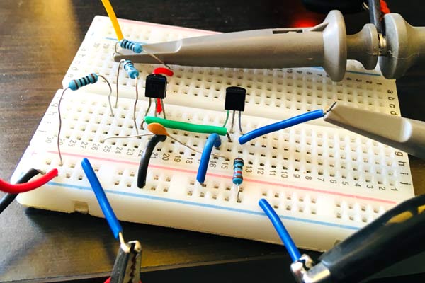
Working of Bootstrap Amplifier
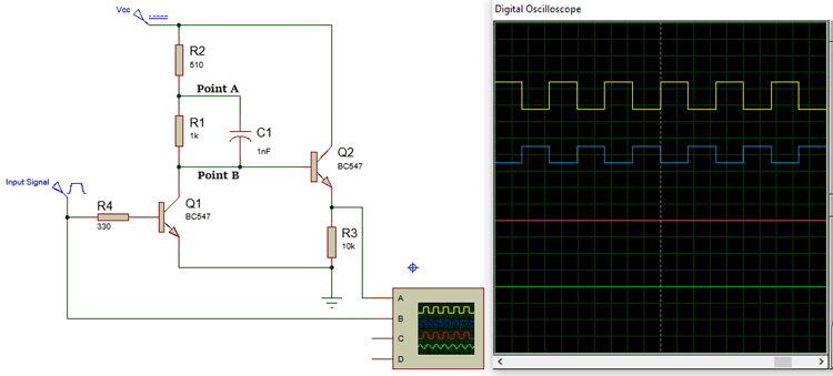
After connecting the circuit as per the circuit diagram, the circuit looks similar to the Darlington pair. Here, we have used bootstrapping technique to increase the input impedance of this amplifier circuit. When the base of the transistor Q1 is high and point B is low. Therefore, the capacitor charges upto the value of voltage across R2. When Q1 goes low and voltage start increasing at the base of Q2, the capacitor discharges slowly. And to maintain the charge, point A is also pushed up. So the voltage at point B increases and the voltage at point A also keeps rising until it goes more than the Vcc.
The charge into the bootstrap capacitor C1 is drained by the resistor R1 and R2. The technique is called as bootstrapping because rising the voltage at one end of the capacitor will increase the voltage at the other end of the capacitor.
Note: Bootstrapping technique can only be used if the RC time constant is more in comparison to the single period of the drive signal.
Below is the proteus simulation of the bootstrap amplifier with the amplified waveform.
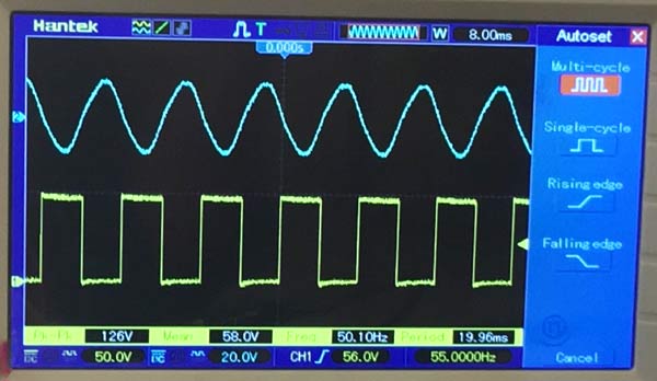
Also, we have designed the bootstrap amplifier circuit on the breadboard. The output waveform obtained using the oscilloscope is given below:
Check more amplifier circuit and their applications.



The circuit above is not bootstrapping. Bootstrapping is a positive feedback.