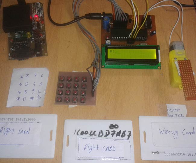
In this project, we are going to develop an RFID and keypad based Security system. This project is implemented by using 8051 microcontroller. RFID Tecnology (Radio Frequency Identification and Detection) is commonly used in schools, colleges, office and stations for various purposes to automatically authenticate people with valid RFID tags. Here we will check the RFID tag, along with a password associated with the tag, to secure the system.
Working
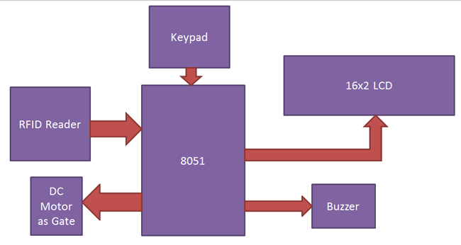
We can divide the complete security system into various sections - Reader section, Keypad, Control section, Driver section and Display section. Working of the entire system and role of each section can be understood throgh the below block diagram.

Reader Section: This section contains a RFID, which is an electronics device which has two parts - one is RFID Reader and other is RFID tag or Card. When we put RFID tag near the RFID reader it reads tag data serially. RFID tag which we have used here has 12 digit character code or serial number. This RFID is working at baud rate of 9600 bps.
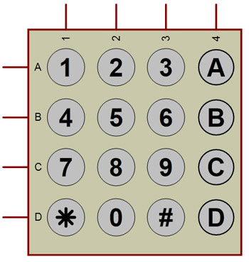
Keypad: Here we have used a 4x4 matrix keypad for entering the password to the system. [Also check: 4x4 keypad interfacing with 8051]

Control Section: 8051 microcontroller is used for controlling the complete process of this RFID based security system. Here by using 8051 we are receiving RFID data and sending status or messages to LCD.
Display Section: 6x2 LCD is used in this project for displaying messages on it. Here you can see the tutorial: LCD interfacing with 8051 microcontroller
Driver Section: This section has a motor driver L293D for opening gate and a buzzer with a BC547 NPN transistor for indications.
When a person put his RFID tag to RFID reader then RFID reads tag’s data and send it to 8051 microcontroller and then microcontroller compares this data with pre-defined data. If data is matched with predefined data then microcontroller ask for password and after entering password microcontroller compare password with predefined password. If password match gate will open otherwise LCD show Access denied and buzzer start beeping for sometime.
Circuit Diagram and Explanation
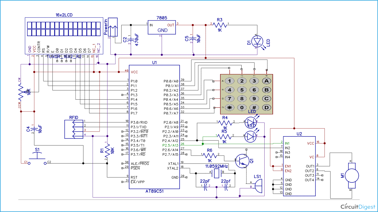
As shown in above RFID security system circuit diagram, 16x2 LCD is connected in four bit mode with microcontroller. LCD’s RS, RW and EN pins are directly connected at PORT 1 pin number P1.0, P1.1 and P1.2. D4, D5, D6 and D7 pins of LCD is directly connected at pin P1.4, P1.5, P1.6 and P1.7 of port 1. Motor driver is connected at PORT pin number P2.4 and P2.5. And buzzer is connected at P2.6 at PORT2. And keypad is connected at PORT0. Keypad row are connected at P0.4 – P0.7 and Columns are connected at P0.0 – P0.3.
Program Explanation
While programming the 8051 microcontroller for RFID based security system, first of all we include header files and defines input and output pin and variables.
#include<reg51.h>
#include<string.h>
#include<stdio.h>
#define lcdport P1

sbit rs=P1^0;
sbit rw=P1^1;
sbit en=P1^2;

sbit m1=P2^4;
sbit m2=P2^5;
sbit buzzer=P3^1;

char i,rx_data[50];

char rfid[13],ch=0;

char pass[4];
Then define pins for keypad module.
sbit col1=P0^0;
sbit col2=P0^1;
sbit col3=P0^2;
sbit col4=P0^3;
sbit row1=P0^4;
sbit row2=P0^5;
sbit row3=P0^6;
sbit row4=P0^7;
After this we have created a function for delay.
 void delay(int itime)
{
    int i,j;
    for(i=0;i<itime;i++)
    for(j=0;j<1275;j++);
}
Then we make some function for LCD and initialize lcd function,
void lcd_init(void)
{
    lcdcmd(0x02);
    lcdcmd(0x28);
    lcdcmd(0x0e);
    lcdcmd(0x01);
}
Here we have some function that we have used in our program. In this we have configured 9600bps baud rate at 11.0592MHz Crystal Frequency, and fuction for receiving we are monitoring the SBUF register for receiving data.
void uart_init()
{
 TMOD=0x20;
 SCON=0x50;
 TH1=0xfd;
 TR1=1;
}
char rxdata()
{
  while(!RI);
    ch=SBUF;
    RI=0;
    return ch;
}
After this in main program we have initialized lcd and Uart and then we read the output of RFID when any tag is bring on it. We store this string in an array and then match with predefind array data. And then match the password.
        if(strncmp(rfid,"160066A5EC39",12)==0)
        {
            keypad();
            if(strncmp(pass,"4201",4)==0)
            {
            accept();
            lcdcmd(1);
            lcdstring("Access Granted ");
            lcdcmd(0xc0);
If match occurs then controller opens the gate, otherwise buzzer starts and LCD shows invalid card.
Complete Project Code
#include<reg51.h>

#include<string.h>

#include<stdio.h>

#define lcdport P1
sbit col1=P0^0;

sbit col2=P0^1;

sbit col3=P0^2;

sbit col4=P0^3;

sbit row1=P0^4;

sbit row2=P0^5;

sbit row3=P0^6;

sbit row4=P0^7;
sbit rs=P1^0;

sbit rw=P1^1;

sbit en=P1^2;
sbit m1=P2^4;

sbit m2=P2^5;

sbit buzzer=P3^1;
char i,rx_data[50];
char rfid[13],ch=0;
char pass[4];
 void delay(int itime)

{

    int i,j;

    for(i=0;i<itime;i++)

    for(j=0;j<1275;j++);

}

void daten()

{

    rs=1;

    rw=0;

    en=1;

    delay(5);

    en=0;

}
void lcddata(unsigned char ch)

{

    lcdport=ch & 0xf0;

    daten();

    lcdport=(ch<<4) & 0xf0;

    daten();

}

void cmden(void)

{

    rs=0;

    en=1;

    delay(5);

    en=0;

}
void lcdcmd(unsigned char ch)

{

    lcdport=ch & 0xf0;

    cmden();

    lcdport=(ch<<4) & 0xf0;

    cmden();

}
void lcdstring(char *str)

{

    while(*str)

    {

        lcddata(*str);

        str++;

    }

}
void lcd_init(void)

{

    lcdcmd(0x02);

    lcdcmd(0x28);

    lcdcmd(0x0e);

    lcdcmd(0x01);

}
void uart_init()

{

 TMOD=0x20;

 SCON=0x50;

 TH1=0xfd;

 TR1=1;

}

char rxdata()

{

  while(!RI);

    ch=SBUF;

    RI=0;

    return ch;

}
void keypad()

{

    lcdcmd(1);

    lcdstring("Enter Ur Passkey");

    lcdcmd(0xc0);

    i=0;

    while(i<4)

    {

     col1=0;

     col2=col3=col4=1;

     if(!row1)

     {

        lcddata('1');

        pass[i++]='1';

        while(!row1);

   }


      else if(!row2)

     {

        lcddata('4');

        pass[i++]='4';

        while(!row2);

   }


      else if(!row3)

     {

        lcddata('7');

        pass[i++]='7';

        while(!row3);

   }


      else if(!row4)

     {

        lcddata('*');

        pass[i++]='*';

        while(!row4);

   }


     col2=0;

     col1=col3=col4=1;

     if(!row1)

     {

        lcddata('2');

        pass[i++]='2';

        while(!row1);

   }


      else if(!row2)

     {

        lcddata('5');

        pass[i++]='5';

        while(!row2);

   }


      else if(!row3)

     {

        lcddata('8');

        pass[i++]='8';

        while(!row3);

   }


      else if(!row4)

     {

        lcddata('0');

        pass[i++]='0';

        while(!row4);

   }


     col3=0;

     col1=col2=col4=1;

     if(!row1)

     {

        lcddata('3');

        pass[i++]='3';

        while(!row1);

   }


      else if(!row2)

     {

        lcddata('6');

        pass[i++]='6';

        while(!row2);

   }


      else if(!row3)

     {

        lcddata('9');

        pass[i++]='9';

        while(!row3);

   }


      else if(!row4)

     {

        lcddata('#');

        pass[i++]='#';

        while(!row4);

   }


      col4=0;

     col1=col3=col2=1;

     if(!row1)

     {

        lcddata('A');

        pass[i++]='A';

        while(!row1);

   }


      else if(!row2)

     {

        lcddata('B');

        pass[i++]='B';

        while(!row2);

   }


      else if(!row3)

     {

        lcddata('C');

        pass[i++]='C';

        while(!row3);

   }


      else if(!row4)

     {

        lcddata('D');

        pass[i++]='D';

        while(!row4);

   }

 }


}
void accept()

{

     lcdcmd(1);

     lcdstring("Welcome");

     lcdcmd(192);

     lcdstring("Password Accept");

     delay(200);

}
void wrong()

{

          buzzer=0;

                lcdcmd(1);

                lcdstring("Wrong Passkey");

                lcdcmd(192);

                lcdstring("PLZ Try Again");

                delay(200);

                buzzer=1;

}
void main()

{

    buzzer=1;

    uart_init();

    lcd_init();

    lcdstring("  RFID Based    ");

    lcdcmd(0xc0);

    lcdstring("Security system ");

    delay(400);

    while(1)

    {

        lcdcmd(1);

        lcdstring("Place Your Card:");

        lcdcmd(0xc0);

        i=0;

        for(i=0;i<12;i++)

        rfid[i]=rxdata();

        rfid[i]='\0';

        lcdcmd(1);

        lcdstring("Your ID No. is:");

        lcdcmd(0xc0);

        for(i=0;i<12;i++)

        lcddata(rfid[i]);

        delay(100);

        if(strncmp(rfid,"160066A5EC39",12)==0)

        {

            keypad();

            if(strncmp(pass,"4201",4)==0)

            {

            accept();

            lcdcmd(1);

            lcdstring("Access Granted ");

            lcdcmd(0xc0);

            lcdstring("Person1");

            m1=1;

            m2=0;

            delay(300);

            m1=0;

            m2=0;

            delay(200);

            m1=0;

            m2=1;

            delay(300);

            m1=0;

            m2=0;

          }

            else

            wrong();

        }


        else if(strncmp(rfid,"160066BD7AB7",12)==0)

            {

            keypad();

            if(strncmp(pass,"4202",4)==0)

            {

            accept();

            lcdcmd(1);

            lcdstring("Access Granted ");

            lcdcmd(0xc0);

            lcdstring("Person2");

            m1=1;

            m2=0;

            delay(300);

            m1=0;

            m2=0;

            delay(200);

            m1=0;

            m2=1;

            delay(300);

            m1=0;

            m2=0;

          }

            else

            wrong();

      }


                else if(strncmp(rfid,"160066203060",12)==0)

            {

    keypad();

            if(strncmp(pass,"4203",4)==0)

            {

            accept();

            lcdcmd(1);

            lcdstring("Access Granted ");

            lcdcmd(0xc0);

            lcdstring("Person3");

            m1=1;

            m2=0;

            delay(300);

            m1=0;

            m2=0;

            delay(200);

            m1=0;

            m2=1;

            delay(300);

            m1=0;

            m2=0;

          }

            else

            wrong();

      }
        else

        {

           lcdcmd(1);

           lcdstring("Access Denied");

           buzzer=0;

           delay(300);

           buzzer=1;

        }

  }

}
Comments
you can convert above C code
you can convert above C code into hex file using keil uvisio software.
hello :) can i know what name
hello :) can i know what name of component label as U2?
ok TQ =) if I using proteus
ok TQ =) if I using proteus to draw and run this circuit, what should I type in proteus library to find RFID?
code not correct
your program have errors so plzz send original code
Sir can you provide the hex
Sir can you provide the hex code . Is this code can be compiled in any c complier or any specific compiler is there?
If i wanted to add more tags
If i wanted to add more tags and passwords how will i do that? and how many persons can you store?
Currently we have hard coded
Currently we have hard coded the the RFID tags IDs so you cant add on run time, but you can alter ID in code for your card. Or you can modify the code to add IDs on run time and share here for the community.
What RFID module is that
What RFID module is that where can i get it from? also tags?
Its 'Em18 Rfid Card Reader
Its 'Em18 Rfid Card Reader Module', you can buy it online or from Local electronic components shop.
Pl Read
Dear Abi
I am Pradeepkumar working in Salem Steel Plant as Sr Mgr Electrical. I started my Carrier in Electronic Lab and having more interest in doing projects as hobby. Earlier I did in 8085 ..then small projects in 89c51 ...now started learning Arduino. I used to invest money to purchase sensors and processor and doing myself in House. But main technical supports are from NET, like you people. But now-a-days people are crazy to put their project as youtube without code and circuit diagram. So some time people like me are blinking.
But you have given the project in detail. It is very nice of you. By your this type of helping, you can develop many electronic engineers in India. let me once again Congrads you abi. All the best. Pl send your mail id if u like to have contact to my mail id []. Thanks Abi
Regard from Pradeep
Is this a correct code or is
Is this a correct code or is it having any errors.?? If so please send me the correct code... If possible hex file
in power section, what type
in power section, what type of power source you use? is it 9v battery?
Sir,
Sir,
I tried the same code given above, but could not understand the flaws.... the rfid reader reads the tag code... but does not display the rfid code in lcd... it shows junk characters..... would you mind helping me out... that what would be reason behind this issue
rfid& microcontrolle
microcontroller size is 4k and program size is 4.59 so the microcontroller does not work?
I'm doing this project and I
I'm doing this project and I want a schematic file to run a proteus simulation.Can u please email me the file.
Rfid reader details
what is the conponent specification used as rfid reader?
eeprom based writing 4 Mobile no. And read it -
Sir I need a code for storing 4 mobile no. After loading the hex file ,the no.has editable via key pad
can u send circuit diagram of rfid
Can u please send the rfid pins connected to the circuit iam using RC522 a bit confusing with the pins.Since there are 8 pins in it.
Thank you
hello, I had made this
hello, I had made this project but the display is not showing output , it only glows when power is given. Can you please tell me the solution for that as soon as possible
KEYPAD connection
The connection of the keypad to the MCU from Port 0 is not functioning for me neither the passkey is appearing on the LCD, any suggestion plz
I want to design this project
I want to design this project for final thesis please help me I get the full document with the system code
I want to design this project
I want to design this project for final thesis please help me how I get the full document with the system codes


GR8 WORK ,KEEP IT UP